
PAGE: 7 / 9
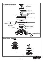
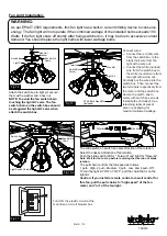
Switch Box
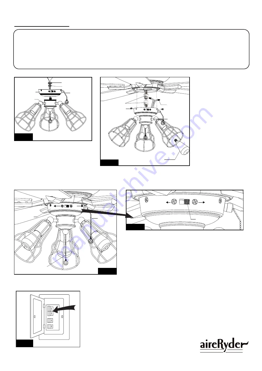
Screw
ST 48 Bulb Max.60W
(Included)
Switch Box
Slide Switch
Forward
Slide Switch
Forward
The slide switch on switch box sets direction of fan rotation.
Select the desired direction of fan rotation.
Push the slide switch left for " Forward" and right for "Reverse".
Note: Wait for fan to stop before reversing the direction of blade
rotation.
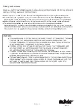
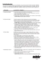
The pull chain controls the fan speed as follows:
1 pull – High, 2 pull – Medium, 3 pull – Low, and 4 pull – Off.
To turn the light kit “ON” or “OFF”, pull the chain that is on the
light kit.
Caution: If you install a remote control or a wall control for
this fan, pull the pull chains to “high speed” of the fan
motor and “on” of the fan light.
Fan Switch
Chain
Fan Switch
Chain
Light Switch Chain
F A N C O
160310
Fan Light Installation:
WARNING:
As per EPACT 2005 requirements, this fan light has a built-in current limiting device to conserve
energy. The fan light will not operate if the combined wattage of the installed bulbs exceeds 190
Watts. If the fan light shuts off shortly after being switched on, it may be due to excessive current
demand. You should replace the light bulbs with lower wattage bulbs.
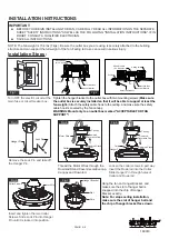
Fig.15
Fig.16-a
Fig.16-b
Fig.17
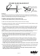
Turn ON the electric circuit at the
main fuse or circuit breaker box.
Terminals
Light Kit
Reverse
Reverse
Fig.14
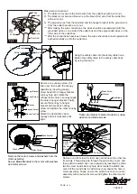
Attach the switch box to light kit, secure
them with a washer and a hex nut.
NOTE: To avoid the fan switch chain
touching the light kit's arm. The fan
switch chain on the switch box should
be staggered the light kit's arm when
attach the switch box.
Light Kit
Switch Box
Hex Nut
Washer
Connect wires :
--- Connect the red (hot) wire
from the switch box to the
black (hot) wire from fan
light with a wire nut.
--- Connect the white (neutral)
wire from the switch box to
the white (neutral) wire from
fan light with a wire nut.
Carefully put the wires into the
switch box. Then connect the
two terminals respectively from
the motor and the switch box.
Secure the switch box to
motor with switch box screws.
Install bulbs (included). See
relamping label at socket
area or packaging for
maximum allowed wattage.
Wire Nut


