


PAGE: 7 / 9
F A N C O
171120
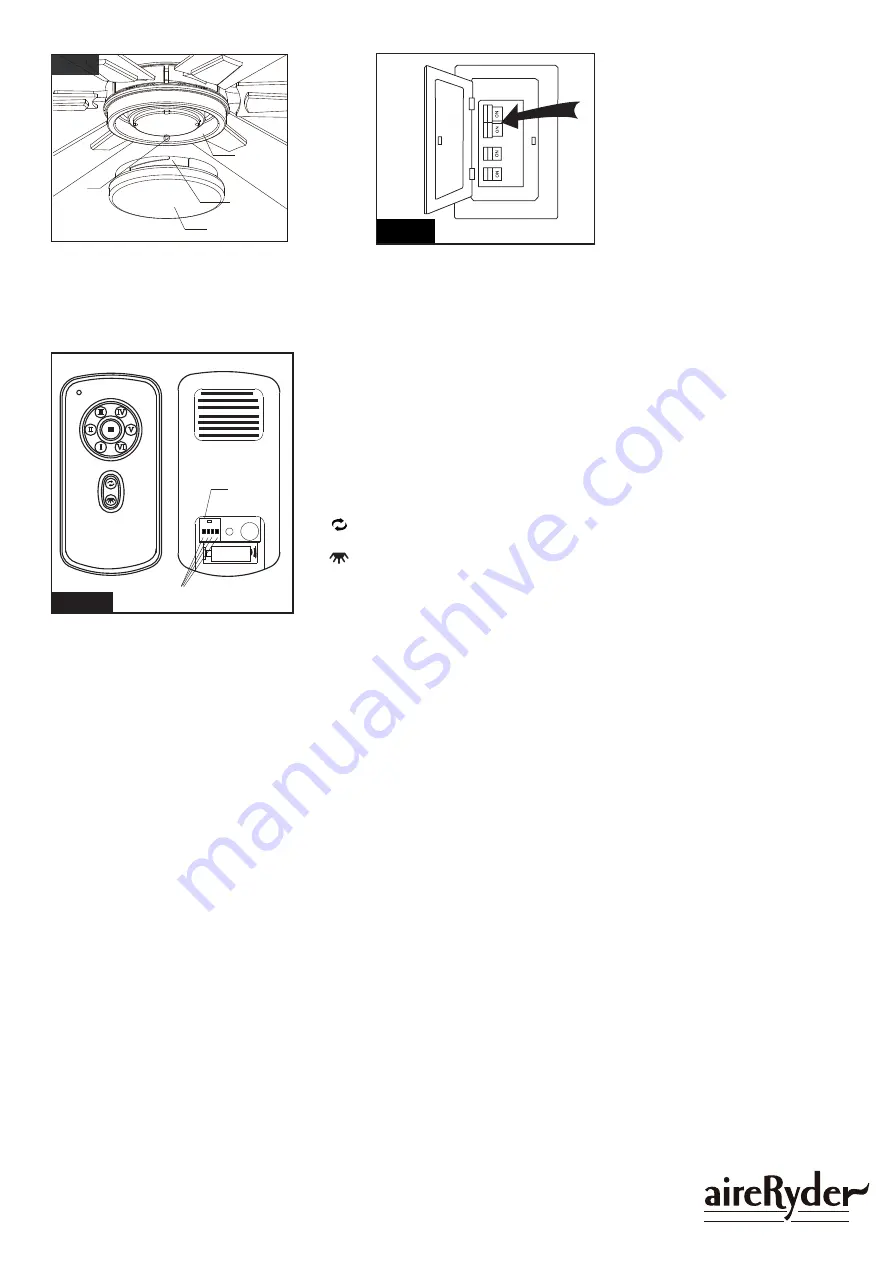
Fig.14
Glass Shade
Slot
Stud
Glass
Holder
Fig.15
Turn ON the electric circuit at the
main fuse or circuit breaker box.
Attach the glass shade to the glass
holder by aligning studs and slots,
and then turn it clockwise until it is
locked in place.
Fig.16
Remote control
Install one 12 volt battery (type 23AE, included) to the remote control.
1. The remote buttons instruct as below:
● Fan speed:
I = minimum speed II = low speed
III = medium low speed IV = medium speed
V = medium high speed VI = high speed
● ■ Button:
This button turns the fan off.
● Reverse button:
This button is to control fan direction.
● Light button:
The button is to control light, Infinite light levels are available by holding the light
on/off button.
2. Frequency Interference (code setting):
Step 1: Turn the power off to your ceiling fan.
Setp 2: Slide code switches on back of remote control.
Step 3: Turn the power on and within 60 seconds, press and hold “SET” button nearby switches. The setup is completed
after the light of the ceiling fan flashes twice.
3. “D” and “ON” dip switch:
The “ON” selection is the light dimmable selection. The “D” selection is the light on only (no dimming function).
Note:The receiver provides protection in the following two situations:
1- Lock protection:The receiver has a built-in protection against obstruction during operation. The motor will be locked and the
power will be disconnected after 30 seconds of obstruction. Please remove obstacles before restarting. To reset, turn off the
power supply to the fan motor, then restart.
2- Power surge protection: If the receiver detects a power consumption of the motor greater than 80W, the power supply will
be interrupted and operation will immediately stop. To reset, turn off the power supply to the fan motor, then restart (after 5
seconds).
3- This remote control has memory function setting. The fan will operate at the same speed and the fan light will stay at the
same brightness as the last time the power supply was turned off.
SET
1 2 3 4
ON
D
Dip Switch
Frequency Code
12V


