
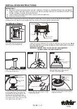
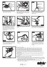

Hang the fan on hanger bracket, and
make sure the slot of hanger ball is
aimed into the chip of hanger bracket
exactly.
Fig.17
Fig.15
Fig.14
Install the hang ball onto the downrod,
then insert the hanger ball pin through
the top hole of the downrod.
Thread the motor wires through the
downrod stand cover, canopy in order.
Thread the motor wires through the
downrod. Then insert the downrod
into the collar.
Fig.16
Tighten the hanger ball screw to the
downrod.
PAGE: 2 / 5
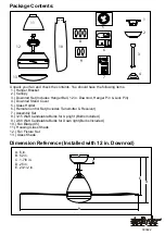
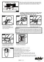
Insert the hanger pin through the holes
in the collar and downrod. Insert the
lock pin through the hole near the end
of the hanger pin until it snaps into its
locked position.
Fig.12
Lock Pin
Downrod
Collar
Glass Holder
House Glass
Shade
Hanger Pin
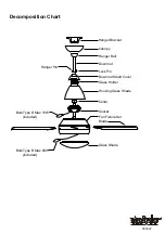
Collar
Collar
Set Screw
Hanger Bracket
Chip
Tighten the downrod set screws on the
collar.
Fig.13
Fig.11
Fig.18
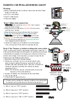
Make wires connections:
1) The white wire from the motor to the white wire from the receiver with a wire nut.
2) The black wire from the motor to the black wire from the receiver with a wire nut.
3) The blue wire from the motor to the blue wire from the receiver with a wire nut.
4) The red wire from the motor to the orange wire from the receiver with a wire nut.
5) The white wire from the outlet box to the red wire from the receiver with "AC in N"
with a wire nut.
6) The black (hot) wire from the outlet box to the red wire from the receiver with "AC in L"
with a wire nut.
7) The ground wire from the outlet box to the green ground wire from the motor with
a wire nut.
Make sure all of wire nuts are connected exactly.
*** After making the wire connections, the wires should be spread apart with the grounded
conductor and the equipment-grounding conductor on one side of the outlet box and the
ungrounded conductor on the other side of the outlet box.
*** After the splices have been made, they should be turned upward and pushed
carefully up into the outlet box.
Use the reverse switch to turn the fan
spin to difference direction.
Housing Glass
Shade
Big Notch
Reverse Switch
Collar
Fig.9
F
A N C O
F
A N C O
090622
Secure the glass holder to the housing
glass shade using the screws provided,
but not over tighten.
Screw
Fig.10


