and use the housing as a template to mark the required
cut out in the ceiling.
5. After cutting out the required area, install the housing
using the hanging brackets as described above.
Ducting
NOTE
: All ducting must comply with local building codes.
1. Connect the correct ducting to the fan (model AK100L
comes complete from the factory with a 4” duct collar),
secure in place using duct tape or a screw clamp. Always
duct these fans to the outside through the wall or roof
cap. To ensure maximum air delivery keep the length of
duct and number of elbows to a minimum.
Electrical Wiring
CAUTION
: Make sure the power is switched off before
beginning this installation.
NOTE
: All wiring must comply with local and national
codes. You must ground this unit.
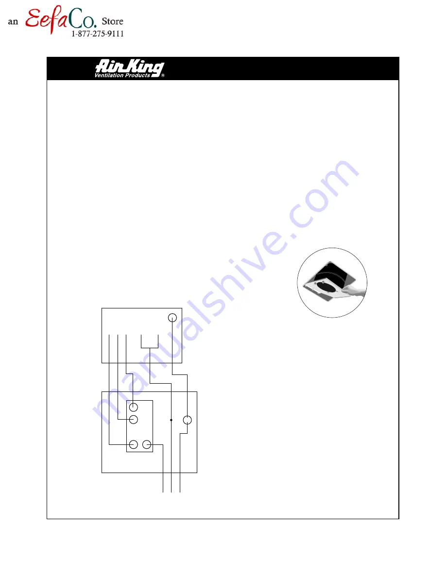
1. Run wiring from the wall switch (not provided) to the
housing electrical compartment, 1 neutral (white), 1
ground (green or bare copper), and 3 hot (black leads
connected to the switch). Make sure you identify which
wire is for which component. Secure the electrical wires
to the housing with an approved electrical connector
(make sure you leave enough wiring in the box to make
the connection to the fan’s receptacle and the light’s
receptacle).
2. From where you have access to inside the fan’s junction
box, connect the white wire from the house to the white
wire of the fan’s receptacle and the light’s receptacle, then
connect one black wire to the house wire intended for
fan control, connect the yellow wire to the house wire
intended for main lighting control and connect the red
wire to the house wire intended for night lighting control
(use approved electrical connectors). Connect the ground
wire to the green ground screw in the fan’s junction box.
Replace the fan’s wire compartment cover.
Completing the
Installation
1. After you have
installed the housing
in the ceiling, run
ducting from the unit
to the outside and
have made the
necessary electrical
connections you can
reinstall the light
housing, venturi and blower in the fan housing (fig. 3).
Plug the fan’s blower assembly into the fan’s receptacle
before you lift the venturi/blower assembly up into
possition and secure the venturi using the screw removed
earlier. Plug the light housing into the intended wiring
harness after the venturi is secure. Rotate the blower
wheel by hand to ensure it revolves freely. Install a 100
watt bulb max. and a 7 watt bulb max. for night lighting.
2. To install the grill, squeeze the two ends of each spring
fastener together and insert each into the slots on the
venturi. Push the grill up to the ceiling. Before cleaning
or relamping turn off the power to the unit. To change
bulbs just remove the grill.
INSTALLATION
INSTRUCTIONS
FAN
ELECTRICAL
BOX
HOUSE
ELECTRICAL
BOX
AK100L WIRING DIAGRAM
120V 60HZ
LIGHT
FAN
GROUND
GROUND
TRIPLE
SWITCH
BLK
WHT
GRD
YELLO
W
RED
WHT
WHT
BLK
NIGHT
LIGHT
Fig. 3


