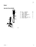
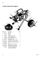
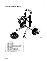
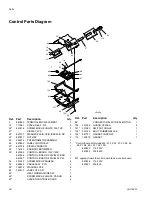
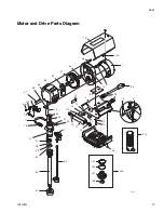
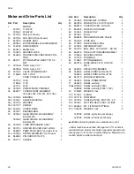
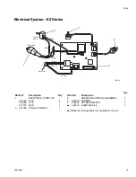
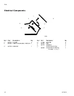
Parts
3A1182G
33
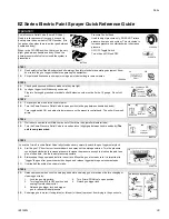
EZ Series Electric Paint Sprayer Quick Reference Guide
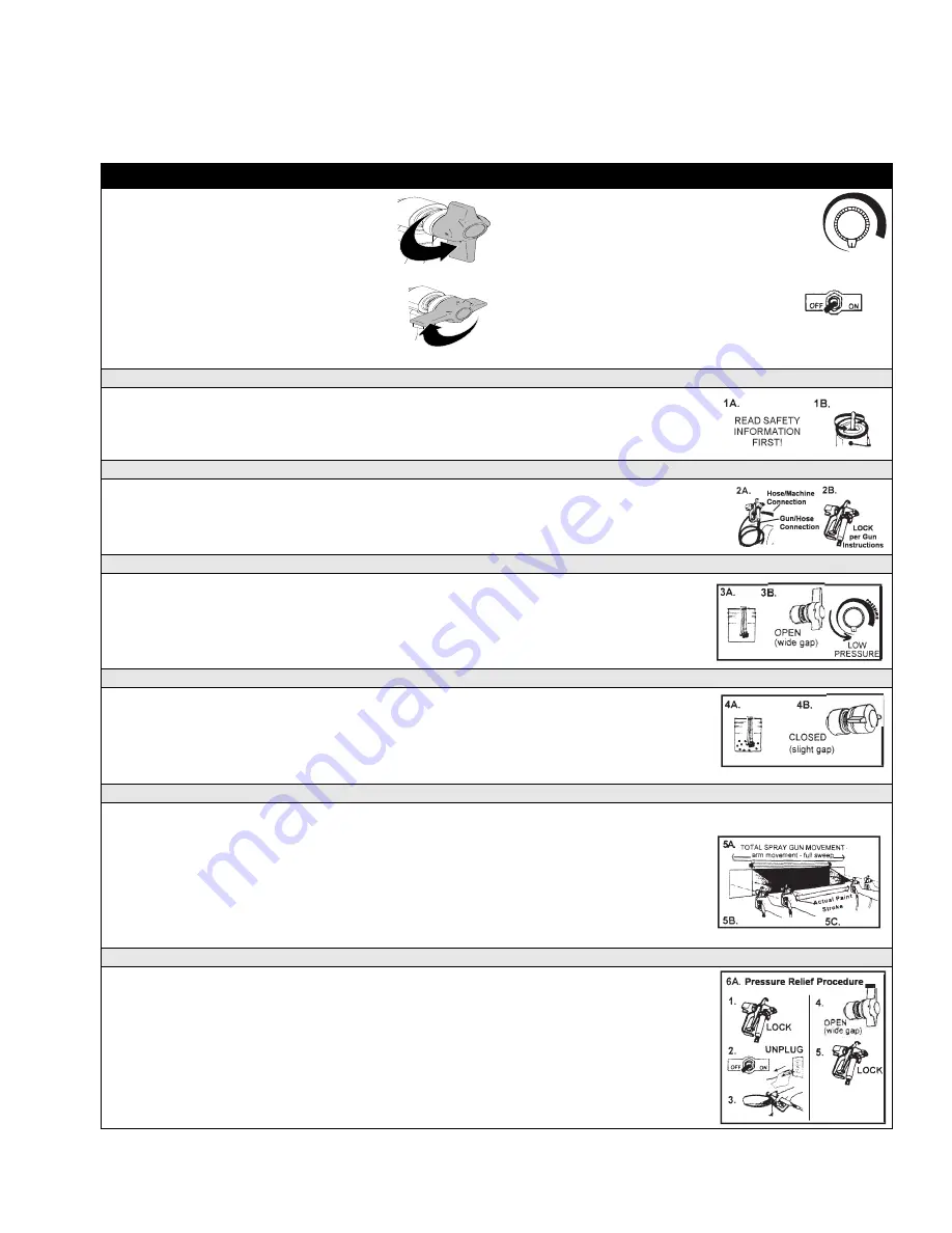
Operation
Prime Pressure Relief Valve (Prime-PR Valve)
Used to relieve pressure from gun, hose and tip
and to prime the unit when in OPEN position. (It is
in open position when there is a wider gap between
handle and body).
Pressure Control Knob
Used to adjust pressure only. DOES NOT relieve
pressure from gun and system. Turn clockwise to
increase pressure, counterclockwise to decrease
pressure.
When in the CLOSED position, there is only a very
slight gap between handle and body. When the
prime/pressure relief valve is closed the system is
pressurized.
ON/OFF Toggle Switch
Turns the unit ON and OFF
STEP 1
1A.
Read safety rules! Read & understand all warnings & safety rules before operating equipment. Know
how to lock the gun trigger lock before operating the equipment.
1B.
Stir paint and if necessary strain paint using a paint strainer bag to remove lumps.
STEP 2
2A.
Check gun/hose connections to make sure they are tight.
2B.
Lock gun trigger lock (Airlessco gun shown).
Plug into 3 pronged grounded electrical outlet. Extension cord must be 3 wire, 12 gauge. Do not coil
cord.
STEP 3
3A.
Put pump suction tube into bucket of paint.
3B.
Turn the Prime-Pressure Relief Valve to open position (wide gap between handle and body).
Turn toggle switch ON, and adjust to low pressure on the pressure control knob. The unit will now self
prime.
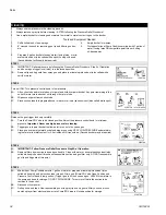
STEP 4
4A.
Wait about one minute until fluid comes out of the return tube (smaller diameter tube).
4B.
Turn the Prime-Pressure Relief Valve to closed position. (slight gap between handle and body)
The
unit is now pressurized.
STEP 5
Leave the Prime-Pressure Relief Valve fully closed and very carefully unlock the gun trigger safety lock.
5A.
Aim the gun 12” from test surface cardboard and spray out the storage solution. Turn the pressure
control knob clockwise to increase pressure. Increase the pressure enough to atomize the paint and
give a full pattern. Use the lowest pressure possible.
5B.
Always keep the gun perpendicular to the surface. Move the gun at a steady rate. It is important to
“trigger” the gun after gun movement has begun and release trigger before gun movement ends.
5C.
Overlap half the width of each paint stroke.
STEP
6
6A.
Release pressure when you stop spraying and before servicing gun or machine or before changing or
cleaning gun tip by:
1.
Lock the gun trigger lock.
2.
Turn toggle switch to OFF position and
unplug from electrical outlet.
3.
Release gun trigger lock and trigger
gun to relieve residual pressure
4.
Turn Prime/PR Valve to open position.
5.
Relock gun trigger lock
6B.
Submerge gun in water (if using latex) or thinner (oil-base) to prevent from drying in the gun nozzle.
ti14791a
ti16048a
ti14790a
ti16067a
ti16068a
ti16069a
ti16070a
ti16071a
ti16072a
ti16073a
ti16066a


