background image

Warnings 

4

3A4180C

Warnings

The following warnings are for the setup, use, grounding, maintenance, and repair of this 

equipment. The exclamation point symbol alerts you to a general warning and the hazard 

symbols refer to procedure-specific risks. When these symbols appear in the body of this 

manual or on warning labels, refer back to these Warnings. Product-specific hazard symbols 

and warnings not covered in this section may appear throughout the body of this manual where 

applicable.

GROUNDING

This product must be grounded. In the event of an electrical short circuit, grounding reduces 

the risk of electric shock by providing an escape wire for the electric current. This product is 

equipped with a cord having a grounding wire with an appropriate grounding plug. The plug 

must be plugged into an outlet that is properly installed and grounded in accordance with all 

local codes and ordinances.

Improper installation of the grounding plug is able to result in a risk of electric shock. 

When repair or replacement of the cord or plug is required, do not connect the grounding 

wire to either flat blade terminal. 

The wire with insulation having an outer surface that is green with or without yellow stripes 

is the grounding wire.

Check with a qualified electrician or serviceman when the grounding instructions are not 

completely understood, or when in doubt as to whether the product is properly grounded. 

Do not modify the plug provided; if it does not fit the outlet, have the proper outlet installed 

by a qualified electrician.

This product is for use on a nominal 120V or 230V circuit and has a grounding plug similar 

to the plugs illustrated below.

Only connect the product to an outlet having the same configuration as the plug.

Do not use an adapter with this product.

Extension Cords:

Use only a 3-wire extension cord that has a grounding plug and a grounding receptacle that 

accepts the plug on the product.

Make sure your extension cord is not damaged. If an extension cord is necessary use 12 

AWG (2.5mm

2

) minimum to carry the current that the product draws.

An undersized cord results in a drop in line voltage and loss of power and overheating.

ti24583a

230V

230V ANZ

120V US

Summary of Contents for MP 455

Page 1: ...architectural paints and coatings MP 455 Mustang 4850 Models 3300 psi 22 7 MPa 227 bar Maximum Working Pressure Important Safety Instructions Read all warnings and instructions in this manual and in related manuals Be familiar with the controls and the proper usage of the equipment Save these instructions ti29449a Related Manuals 3A4133 Gun 3A4347 Pump www graco com techsupport ...

Page 2: ...nstallation 18 Spray 18 Clear Tip Clog 19 Cleanup 19 Maintenance 22 Troubleshooting 23 Mechanical Fluid Flow 23 Electrical 26 Stand Sprayer Parts 30 Stand Sprayer Parts 31 Stand Sprayers Parts List 32 Hi Boy Sprayers Parts 33 Hi Boy Sprayers Parts 34 Hi Boy Sprayers Parts List 35 Accessories and Labels 36 Control Box and Filter 37 Control and Filter Parts List 38 Wiring Diagrams 39 120V 39 230V 40...

Page 3: ...Models 3A4180C 3 Models VAC Model Stand Hi Boy 120 USA MP455 17M132 17M133 Mustang 4850 17M149 17M150 230 Asia ANZ South America MP455 17M235 17M236 ...

Page 4: ...hen repair or replacement of the cord or plug is required do not connect the grounding wire to either flat blade terminal The wire with insulation having an outer surface that is green with or without yellow stripes is the grounding wire Check with a qualified electrician or serviceman when the grounding instructions are not completely understood or when in doubt as to whether the product is prope...

Page 5: ...dure for turning off the unit and relieving the pressure before removing the nozzle tip to clean Equipment maintains pressure after power is shut off Do not leave the equipment energized or under pressure while unattended Follow the Pressure Relief Procedure when the equipment is unattended or not in use and before servicing cleaning or removing parts Check hoses and parts for signs of damage Repl...

Page 6: ...pray area when spraying flushing cleaning or servicing Do not spray pump assembly Do not smoke in the spray area or spray where sparks or flame is present Do not operate light switches engines or similar spark producing products in the spray area Keep area clean and free of paint or solvent containers rags and other flammable materials Know the contents of the paints and solvents being sprayed Rea...

Page 7: ...utate fingers and other body parts Keep clear of moving parts Do not operate equipment with protective guards or covers removed Pressurized equipment can start without warning Before checking moving or servicing equipment follow the Pressure Relief Procedure and disconnect all power sources TOXIC FLUID OR FUMES HAZARD Toxic fluids or fumes can cause serious injury or death if splashed in the eyes ...

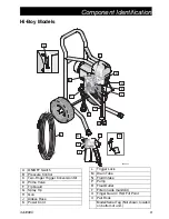
Page 8: ... Switch B Pressure Control C Two Finger Trigger Conversion Kit D Prime Valve F Tip Guard G Spray Tip H Gun J Airless Hose K Power Cord L Trigger Lock M Drain Tube N Fluid Intake P Pump R Fluid Outlet S Power Cord Wrap U Filter inside manifold V Finger Guard TSO Fill Point Model Serial Tag Not shown located on bottom of unit ...

Page 9: ... Pressure Control C Two Finger Trigger Conversion Kit D Prime Valve F Tip Guard G Spray Tip H Gun J Airless Hose K Power Cord L Trigger Lock M Drain Tube N Fluid Intake P Pump R Fluid Outlet T Filter inside manifold U Finger Guard TSO Fill Point V Pail Hook Model Serial Tag Not shown located on bottom of unit ...

Page 10: ...duce sprayer performance Pails Solvent and oil based fluids follow local code Use only conductive metal pails placed on a grounded surface such as concrete Do not place pail on a non conductive surface such as paper or cardboard which interrupts grounding continuity Always ground a metal pail connect a ground wire to the pail Clamp one end to the pail and the other end to a true earth ground such ...

Page 11: ...g Disengage the trigger lock 4 Hold a metal part of the gun firmly to a grounded metal pail Trigger the gun to relieve pressure This equipment stays pressurized until pressure is manually relieved To help prevent serious injury from pressurized fluid such as skin injection splashed fluid and moving parts follow the Pressure Relief Procedure whenever sprayer is stopped and before sprayer is cleaned...

Page 12: ...spray tip or hose is clogged or that pressure has not been fully relieved a VERY SLOWLY loosen the tip guard retaining nut or the hose end coupling to relieve pressure gradually b Loosen the nut or coupling completely c Clear hose or tip obstruction Trigger Lock Always engage the trigger lock when sprayer is stopped to prevent the gun from being triggered accidentally by hand or if dropped or bump...

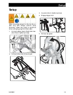
Page 13: ...orm setup procedure When first setup is performed remove shipping plug from fluid outlet 1 Connect airless hose to fluid outlet Use wrenches to tighten securely 2 Connect other end of hose to gun 3 Use wrenches to tighten securely 4 Engage trigger lock 5 Remove tip guard ti29458a ti29455a ti29459a ...

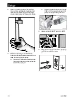
Page 14: ... to prevent premature packing wear Do this daily or each time you spray a Place the TSO bottle nozzle into the top center opening in the grill at the front of the sprayer b Squeeze bottle to dispense enough TSO to fill the space between the pump rod and packing nut seal 8 Make certain ON OFF switch is OFF 9 Plug power supply cord into a properly grounded electrical outlet ti24638a ti29460a ti25130...

Page 15: ...ace fluid intake with drain tube in grounded metal pail partially filled with flushing fluid Use water to flush water based paint or mineral spirits to flush oil based paint 20 Turn ON OFF switch to ON position 21 Turn prime valve horizontal Disengage trigger lock 22 Hold a metal part of the gun firmly to a grounded metal pail Trigger gun and flush for one minute 23 Turn ON OFF switch to OFF posit...

Page 16: ...3 Place fluid intake in paint pail Place drain tube in waste pail 4 Turn ON OFF switch to ON position 5 Turn pressure control 1 2 turn to start motor Allow paint to circulate through sprayer until paint flows out the drain tube 6 Turn prime valve horizontal Disengage trigger lock ti29463a ti25129a ti29464a ti29462a ...

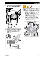
Page 17: ...ks occur perform Pressure Relief Procedure page 12 then tighten all fittings and repeat Startup procedure If there are no leaks continue with the next step 10 Screw tip assembly onto gun and tighten See Spray Tip Installation page 18 For gun assembly instructions see separate gun manual ti24647a 1 m 20s ti29572a High pressure spray is able to inject toxins into the body and cause serious bodily in...

Page 18: ...aller tip size if pressure adjustment cannot eliminate heavy edges 3 Hold gun perpendicular 10 12 in 25 30 cm from surface Spray back and forth overlap by 50 4 Trigger gun after moving Release trigger before stopping For additional spraying information see separate gun manual 0 0 To avoid serious injury from skin injection do not put your hand in front of the spray tip when installing or removing ...

Page 19: ...CLOG NOTE If spray tip is difficult to rotate when turning to the unclog position perform Pressure Relief Procedure page 5 then turn Prime Spray valve to spray position and repeat step 1 2 Engage trigger lock Rotate spray tip back to spray position Disengage trig ger lock and continue spraying SPRAY Cleanup 1 Perform Pressure Relief Procedure page 12 2 Remove tip guard and Spray Tip For additional...

Page 20: ...sure until the pump runs steady and flushing fluid appears 7 Stop triggering gun Move gun to waste pail hold gun against pail trigger gun to thoroughly flush system 8 While continuing to trigger gun turn prime valve down Then release gun trigger Allow flushing fluid to circulate until fluid comes out of drain tube clear 9 Raise fluid intake above flushing fluid 10 Turn prime valve horizontal Trigg...

Page 21: ...e filter from gun and sprayer if installed Clean and inspect Install filter See separate gun manual 14 If flushing with water flush again with mineral spirits or Pump Conditioner to leave a protective coating to prevent freezing or corrosion 15 Wipe sprayer hose and gun with a rag soaked in water or mineral spirits ti29473a ti29475a MANUFACTURED BY ti29476a ...

Page 22: ...t be 1 2 in 13mm minimum length NOTE Brushes do not wear at the same rate on both sides of motor Check both brushes Every 1000 gallons 3785 liters Check sprayer stall With sprayer gun NOT triggered sprayer motor should stall and not restart until gun is triggered again If sprayer starts again with gun NOT triggered inspect pump for internal external leaks and check prime valve for leaks Every 1000...

Page 23: ... clogged Remove and clean then reinstall Intake valve ball and piston ball are not seating properly Remove intake valve and clean Check balls and seats for nicks replace if necessary See pump manual Strain paint before using to remove particles that could clog pump Fluid filter or tip filter is clogged or dirty Clean filter Prime valve leaking Follow Pressure Relief Procedure page 12 then repair p...

Page 24: ... brushes Broken and misaligned motor brush springs Rolled portion of spring must rest squarely on top of brush Replace spring if broken Realign spring with brush Motor brushes are binding in brush holders Clean brush holders remove carbon dust with a small cleaning brush Align brush lead with slot in brush holder to assure free vertical brush movement Motor runs but pump does not stroke Connecting...

Page 25: ...sible during priming Intake valve is leaking Clean intake valve Be sure ball seat is not nicked or worn and that ball seats well Reassemble valve Pump packings are worn Replace pump packings See pump manual Paint is too thick Thin the paint according to supplier recommendations Sprayer operates for 5 to 10 minutes then stops Pump packing nut too tight When pump packing nut is too tight the packing...

Page 26: ... covers are removed for troubleshooting wait 7 seconds after disconnecting power cord for stored electricity to dissipate Problem What to Check How to check Sprayer does not run at all Check electrical supply Make certain that there is AC voltage 100 130V for 110 120VAC models or 210 255V for 230VAC models Check pressure control connections Make certain connector is clean and firmly connected Chec...

Page 27: ...ng to the carbon brushes normally Red and Black Motor should spin when battery is connected to the motor leads Check motor thermal switch Motor should be at ambient temperature for this test Connect the yellow leads from the motor to an Ohm meter Meter should indicate continuity Problem What to Check How to check YELLOW BLACK RED ti25122a 9 VOLT BATTERY YELLOW BLACK RED ti25123a BEEP ...

Page 28: ...while checking for opens If an open is found replace the motor Check for motor short Use an Ohm meter to check motor for shorts Connect meter lead to motor case Move the meter lead to each motor wire Meter should read open on all wires Problem What to Check How to check BLACK RED YELLOW 1 3 ohms ti25124a OL BLACK RED YELLOW ti25125a GROUND ...

Page 29: ...ighten terminal screws Replace brushes if leads are damaged Brushes must be 1 2 in 13mm minimum NOTE Brushes do not wear at the same rate on both sides of motor Check both brushes Replace brushes Broken or misaligned motor brush springs Rolled portion of spring must rest squarely on top of brush Replace spring if broken Realign spring with brush Motor brushes may be binding in brush holders Clean ...

Page 30: ...arts 30 3A4180C Stand Sprayer Parts 47 58 68 71 54a 59 167 23 12 63 53 54 7 168 169 36 95 ti29477a 56 47 4 2 See page 37 2 1 Ref Torque 140 160 in lb 15 8 18 1 N m 30 35 in lb 3 4 4 0 N m 23 27 in lb 2 6 3 1 N m 1 2 4 ...

Page 31: ...ts 3A4180C 31 Stand Sprayer Parts ti29478a 14 4 4 91 41 43 47 28 60 6 6 37 39 145 20 27 42 48 70 65 22 52 12 40 44 1 9 10 8 25 3 4 1 1 1 Ref Torque 140 160 in lb 15 8 18 1 N m Hammer tight 23 27 in lb 2 6 3 1 N m 1 3 4 ...

Page 32: ... ROD connecting 1 44 24X020 GEAR crankshaft includes 25 1 45 15M671 HOSE cpld 1 47 117493 SCREW mach hex washer hd 6 48 113796 SCREW flanged hex 1 49 115495 SCREW mach hex washer hd 2 52 See page 36 LABEL front 1 53 See page 36 LABEL side 1 54 KIT motor electric includes 54a 1 17C794 120V 17C799 230V 54a 17C795 FAN motor roller clutch 1 56 17N718 SHIELD housing 1 58 331048 CAP leg 2 59 17M429 FRAM...

Page 33: ...rts 3A4180C 33 Hi Boy Sprayers Parts 59 36 54a 54 23 95 157 159 158 12 135 133 58 47 7 53 63 ti29480a 4 56 47 2 See page 37 2 1 Ref Torque 140 160 in lb 15 8 18 1 N m 30 35 in lb 3 4 4 0 N m 23 27 in lb 2 6 3 1 N m 1 2 4 ...

Page 34: ...4180C Hi Boy Sprayers Parts 42 43 47 32 49 41 14 45 22 12 70 145 136 160 137 91 60 37 84 62 39 55 52 65 ti29479a 28 27 40 44 1 9 10 8 25 1 4 3 1 1 Ref Torque 140 160 in lb 15 8 18 1 N m Hammer tight 23 27 in lb 2 6 3 1 N m 1 3 4 ...

Page 35: ...R crankshaft includes 25 1 45 15M671 HOSE cpld 1 47 117493 SCREW mach hex washer hd 6 49 115495 SCREW mach hex washer hd 2 52 See page 36 LABEL front 1 53 See page 36 LABEL side 1 54 KIT motor electric includes 54a 1 17C794 120V 17C799 230V 54a 17C795 FAN motor roller clutch 1 55 15K092 TUBE drain 1 56 17N718 SHIELD housing 1 58 331048 BOOT rubber 2 59 17M446 FRAME cart universal 1 60 17C949 TUBE ...

Page 36: ...5 Label Warning Ref 34 Card Medical Alert 17M132 17M133 17M688 17M695 15K359 195793 179960 17M149 17M150 17M706 17M707 15K359 195793 179960 17M235 17M236 17M688 17M695 15H087 195792 17A134 English Spanish French Asia ANZ English Chinese Korean North America Replacement Danger and Warning labels tags and cards are available at no cost ...

Page 37: ...ol Box and Filter 156 90 56 12 12 49 38 20 16 15 19 47 150 5 47 35 36 27 4 29 26 24 51 ti29481a 18 49a 2 7 1 2 9 1 Ref Torque 140 160 in lb 15 8 18 1 N m 30 35 in lb 3 4 4 0 N m 130 150 in lb 14 7 16 9 N m 320 380 in lb 36 2 42 9 N m 1 2 7 9 ...

Page 38: ...SE valve 1 38 KIT control pressure includes 19 20 51 24X289 120V models 1 24X290 230V models 1 47 117493 SCREW mach 2 49 BOARD control 249052 120V 1 16X295 230V includes 49a 1 49a 24R905 BOARD capacitor 230V 1 51 15A464 LABEL control 1 56 CORD power 15J743 120V models 1 253373 230V models 1 90 195551 RETAINER plug adapter on select models 1 150 Fuse replacement 119277 120V models 1 119688 230V mod...

Page 39: ...Wiring Diagrams 3A4180C 39 Wiring Diagrams 120V Red Black Pressure Control Assembly Power Plug White Green Black from Motor 2 x Yellow ON OFF Switch ti5643a Capacitor Replaceable Fuse ti5643a ...

Page 40: ...iring Diagrams 40 3A4180C 230V ti22267b From Motor Replaceable Fuse 2X Yellow Red Red H Brown Blue Green Black Pressure Control Assembly ON OFF switch Red D Black E Red MOV Capacitors Power Plug Black F ...

Page 41: ...and 17 0 in 43 2 cm Hi Boy 23 0 in 58 4 cm Width Stand 14 0 in 35 6 cm Hi Boy 20 5 in 52 1 cm Weight Stand 37 0 lb 16 8 kg Hi Boy 52 0 lb 23 6 kg Noise dBa 70 psi 0 48 MPa 4 8 bar Sound pressure 90 dBa Sound power 100 dBa Materials of Construction Wetted materials on all models zinc and nickel plated carbon steel nylon stainless steel PTFE Acetal leather UHMWPE aluminum tungsten carbide polyethyle...

Page 42: ...Notes 42 3A4180C Notes ...

Page 43: ...clude the costs of parts labor and transportation THIS WARRANTY IS EXCLUSIVE AND IS IN LIEU OF ANY OTHER WARRANTIES EXPRESS OR IMPLIED INCLUDING BUT NOT LIMITED TO WARRANTY OF MERCHANTABILITY OR WARRANTY OF FITNESS FOR A PARTICULAR PURPOSE Airlessco s sole obligation and buyer s sole remedy for any breach of warranty shall be as set forth above The buyer agrees that no other remedy including but n...

Page 44: ...on Airlessco reserves the right to make changes at any time without notice Original Instructions This manual contains English MM 3A4180 GRACO INC AND SUBSIDIARIES P O BOX 1441 MINNEAPOLIS MN 55440 1441 USA Copyright 2016 Graco Inc All Graco manufacturing locations are registered to ISO 9001 Revision C May 2017 Airlessco Information For the latest information about AIRLESSCO products visit www airl...

Reviews: