3. Electric System
3-9
6.List of functions
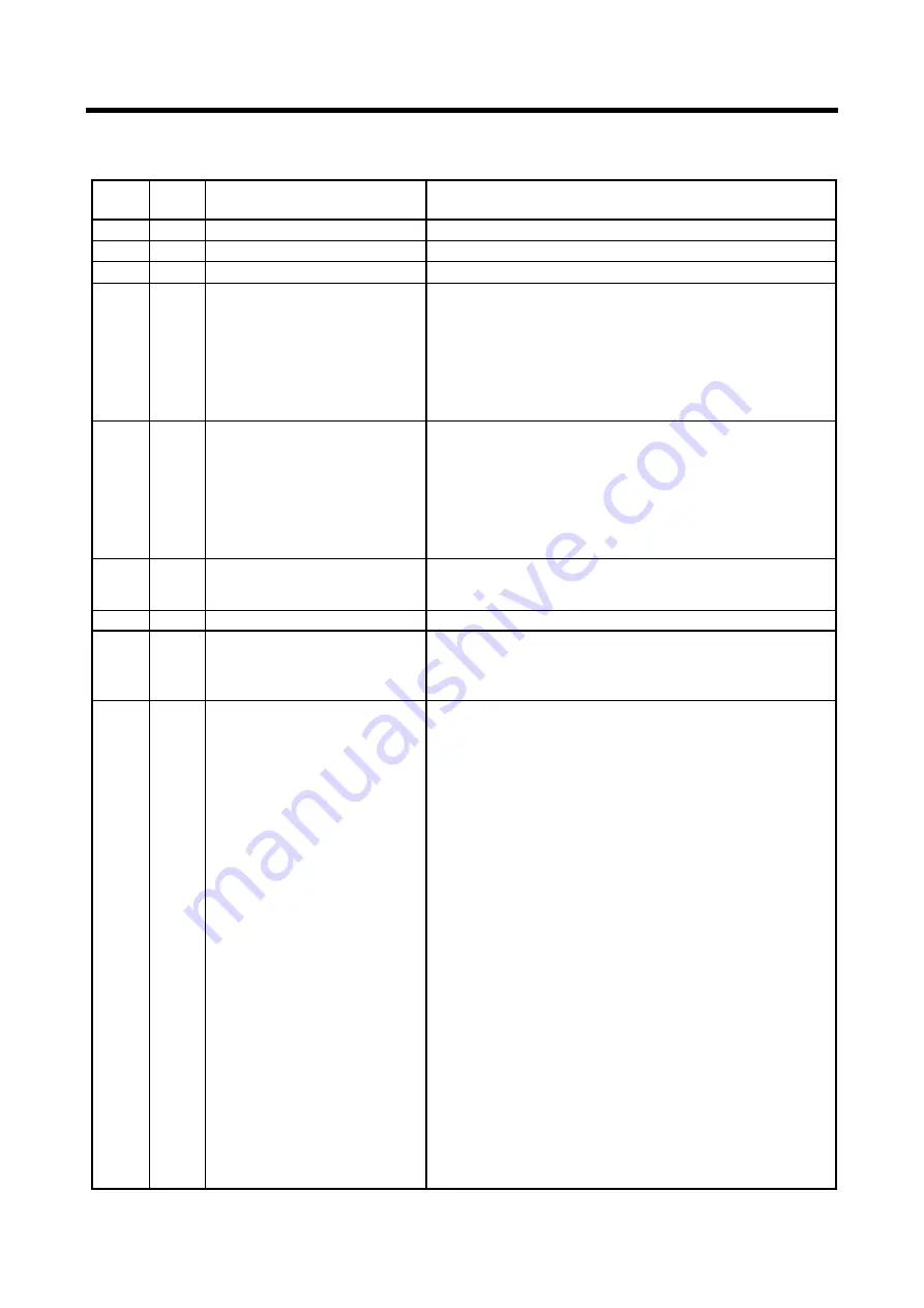
(1)Connector CN1
Pin No.
Line
color
Connection
Remark
1 B
Earth
2
-
NIL
3 B
Earth
4 W/B
Stop solenoid
[Stop motor relay]
When voltage is applied to CN1-8 terminal by
switching “ON” starter switch, voltage is outputted
from CN1-4 terminal, and it actuates stop solenoid
[stop motor relay].
When starter switch is “OFF” or emergency stop device
functions, interior contact (RY1) between CN1-8 and
CN1-4 terminal gets “OFF” to cut electrical supply and
to cause engine to emergency stop.
5
B/Y Starter relay No.3 terminal
Turn starter switch to “START” and then it gets electrically
connected.
(Starting signal inputted from starter relay No.3 terminal is
sent from CN1-3 terminal to ground connector.)
After starting engine, and when alternator generating signal
is inputted to CN2-17 terminal, interior contact (RY2)
between CN1-5 and CN1-3 terminal gets “OFF” to prevent
overrun of starter motor and plunging of pinion gear.
6
R/Y
[R/W]
10A Fuse
(Through joint connector
No.1 terminal)
Power supply
7
-
NIL
8
R/Y
[R/W]
10A Fuse
(Through joint connector
No.6 terminal)
Power supply for actuation of stop solenoid valve
When starter switch turns “ON”, electricity flows
between CN1-8 and CN1-4 terminal to actuate stop
solenoid valve.
9 L/W
Purge/starting unloader
solenoid valve No.1 terminal
When starter switch is switched “ON” and voltage is
applied to CN1-6 terminal, interior contact (RY3)
between CN1-9 and CN1-3 turns “ON” to get
electrically connected and to open the solenoid valve
when engine starts. Thus it starts starting unloader
operation and makes engine smoothly start at light
load.
When CN2-17 terminal receives alternator generating
signal input after engine starts, controller timer starts
to disengage the contact “OFF” in 10 seconds. Then the
electrical connection is cut to close the valve. This
starting unloader operation of this valve is disengaged
and compressor starts normal operation.
●
When AUTO IDLE (PURGE CONTROL) SWITCH is ON
When pushing AUTO IDLE switch during operation, it
will be switched to purge control operation.
When compressor is transferred to unloaded operation
by reduction of air consumption and intake negative
pressure at secondary aide increases. During operation
of purge control, this sensor detects this negative
pressure and outputs it to controller for operation
control. When the intake valve to controller passes
under the set pressure (standard value: negative
pressure 30%) for a certain time, the interior contact
(RY3) turns “ON”. Thus purge/starting unloader
solenoid valve is electrically connected to open the
valve to reduce the pressure in receiver tank and
switched to purge operation.
The data in [ ] show those of electric apparatus used for PDS185S-6C1R. (IN LINE PUMP type).
Discount-Equipment.com
Summary of Contents for PDS185S-6C1
Page 1: ...D i s c o u n t E q u i p m e n t c o m...
Page 19: ...1 Specification 1 15 1 7 Piping Diagram PC08091E D i s c o u n t E q u i p m e n t c o m...
Page 76: ...5 4 PDS185S 6C1 VE PUMP Type PC08047E D i s c o u n t E q u i p m e n t c o m...
Page 77: ...5 5 PDS185S 6C1R IN LINE PUMP Type PC08048E D i s c o u n t E q u i p m e n t c o m...
Page 78: ...5 6 PDS185S 6C1R IN LINE PUMP Type PC08090E D i s c o u n t E q u i p m e n t c o m...


