3. Electric System
3-23
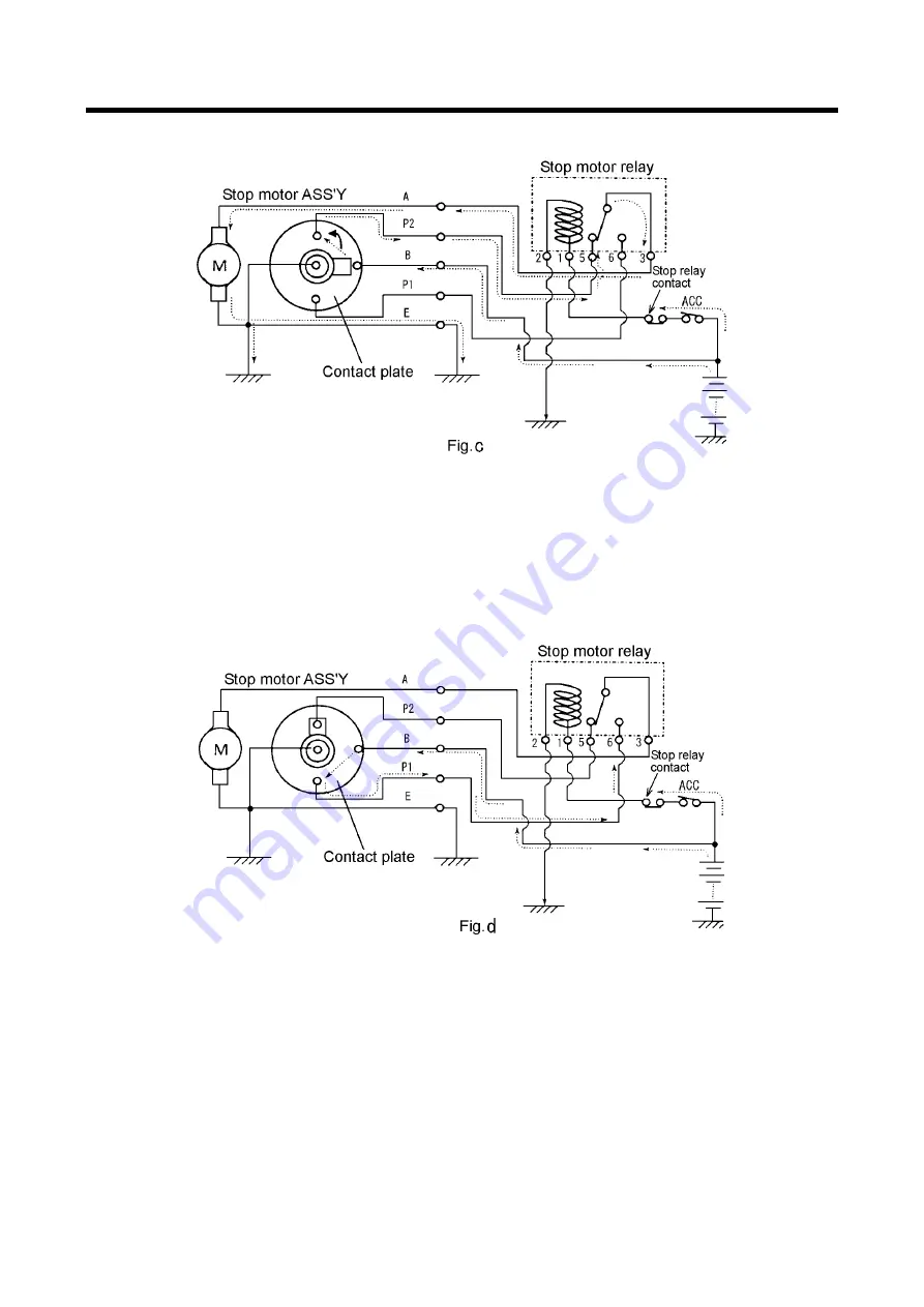
3. Rotation of contact plate
PC08043E-1
①
When motor begins to rotate, the worm fitted to the motor shaft rotates and at the same time
worm wheel rotates.
②
The worm wheel and contact plate are interconnected and so it continues to rotate as shown in
Fig C.
4. Stop of contact plate rotation
PC08044E-1
①
When the contact plate turns 180
˚
degree from the state at which it stays, the electrical
conduction disappears between B and P2 terminal as shown in Fig.d, P2 terminal is connected to
the grounding side. Further, it follows that the armature of the motor gets short-circuited and so
it is electrically braked so that the contact plate stops surely at the constant position
②
At the same time worm rotation is reduced by worm wheel, and further the rotation will be
changed for reciprocal movement via the lever. The stroke extends the wire to move the fuel
lever fitted at the injection pump to open the fuel circuit.
③
When the contact plate stays at the position shown in fig d, the conduction appears between B
and P1 terminal and so the voltage of battery is applied to stop motor relay No.6 terminal.
Discount-Equipment.com
Summary of Contents for PDS185S-6C1
Page 1: ...D i s c o u n t E q u i p m e n t c o m...
Page 19: ...1 Specification 1 15 1 7 Piping Diagram PC08091E D i s c o u n t E q u i p m e n t c o m...
Page 76: ...5 4 PDS185S 6C1 VE PUMP Type PC08047E D i s c o u n t E q u i p m e n t c o m...
Page 77: ...5 5 PDS185S 6C1R IN LINE PUMP Type PC08048E D i s c o u n t E q u i p m e n t c o m...
Page 78: ...5 6 PDS185S 6C1R IN LINE PUMP Type PC08090E D i s c o u n t E q u i p m e n t c o m...


