3. Electric System
3-24
5. Engine stops (normal stop)
PC08045E-1
①
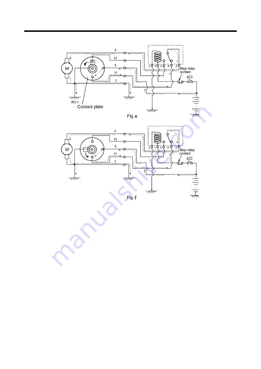
To stop engine, handle starter switch to open ACC contact (“Stop” position) so that excitation
circuit of stop motor relay may be released to move the contact point as shown in Fig e.
②
As the voltage of battery is already applied to stop motor relay No.6 terminal, the circuit of stop
motor relay No.3 terminal
→
stop motor A terminal
→
motor
→
grounding is formed and so the
motor turns and at the same time the contact plate also turns as shown in the fig f.
③
The contact plate continues to turns from 180
˚
position shown Fig e to the 360
˚
position in Fig a
via Fig f position. At the same time when the contact plate rotates the wire is pulled to close fuel
line circuit by the fuel line connected to injection pump to close the fuel circuit to stop engine.
④
Motor and contact plate stop to rotate at specified position in Fig a, and return to the position in
the clause “ 1. Before engine starts ”.
6. Emergency stop
When any abnormalities are found in engine oil pressure, water temperature and discharge air
temperature, controller emergency stop circuit functions, interior contact (RY1) starts to function to
open the switch and to release stop motor relay exciting circuit. The process till “5.engine stops” is
same after engine stop (normal stop).
Discount-Equipment.com
Summary of Contents for PDS185S-6C1
Page 1: ...D i s c o u n t E q u i p m e n t c o m...
Page 19: ...1 Specification 1 15 1 7 Piping Diagram PC08091E D i s c o u n t E q u i p m e n t c o m...
Page 76: ...5 4 PDS185S 6C1 VE PUMP Type PC08047E D i s c o u n t E q u i p m e n t c o m...
Page 77: ...5 5 PDS185S 6C1R IN LINE PUMP Type PC08048E D i s c o u n t E q u i p m e n t c o m...
Page 78: ...5 6 PDS185S 6C1R IN LINE PUMP Type PC08090E D i s c o u n t E q u i p m e n t c o m...


