background image

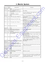
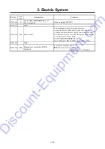
3. Electric System 

3-35 

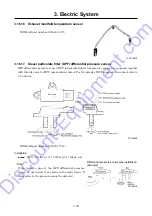
3.16.4


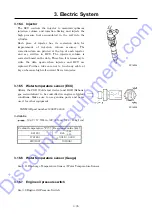
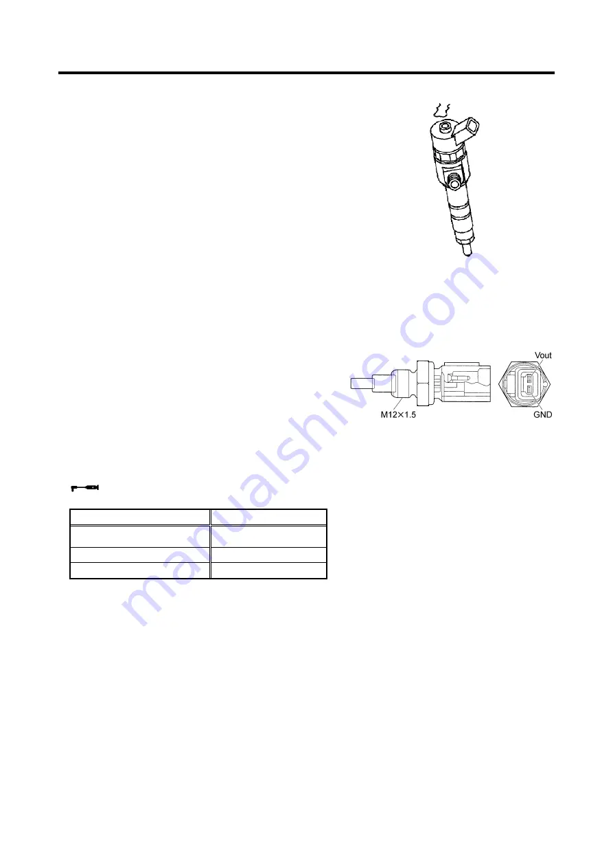
Injector 

The ECU controls the injector to maintain optimum 
injection volume and injection timing and injects the 
high pressure fuel accumulated in the rail into the 
cylinder. 
Each piece of injector has its correction data for 
improvement of injection volume accuracy. The 
correction data are printed at the top of each injector, 
and are written in ECU. The injection volume is 
corrected based on the data. Therefore, it is necessary to 
write the data again when injector and ECU are 
replaced. Further, take care not to touch any cable at 
key on because high volt current flows to injector. 


3.16.5


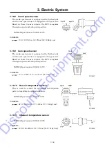
Water temperature sensor (ECU) 

Allows the CSD (Cold start device) and EGR (Exhaust 
gas recirculation) to be controlled in engine cold-start 
conditions. Make sure to use genuine parts and never 
use it for other equipment. 


YANMAR part number:129927-44900 


Installation 

194.7

±

17.7lbf

in. (22

±

2N

m) [224

±

20kgf

cm] 


Coolant temperature °F(

)  Resistance value (k

Ω

)

 68( 20) 

2.45

0.14

0.13

176( 80) 

0.318

±

0.008 

212(100) (0.1836) 


3.16.6


Water temperature sensor (Gauge) 


See 3.11 Discharge Temperature Sensor / Water Temperature Sensor. 


3.16.7


Engine oil pressure switch 


See 3.9 Engine Oil Pressure Switch. 


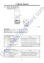
PC14034


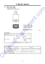
PC14035

Discount-Equipment.com

Summary of Contents for PDS185S-6E1

Page 1: ...www discount equipment com D i s c o u n t E q u i p m e n t c o m...

Page 2: ...ie Terex JLG MultiQuip Mayco Toro Stone Diamond Products Magnum Airman Mustang Power Blanket Nifty Lift Atlas Copco Chicago Pneumatic Allmand Brothers Essick Miller Spreader Skyjack Lull Skytrak Tsuru...

Page 3: ...we request you to make sure to start the job after clarifying it Service personnel is required to safely take quick and proper countermeasures as well as to use correct technology of maintenance in ca...

Page 4: ...and Vacuum Relief Valve 2 11 2 8 Maintenance and Adjustment of Pressure Control Valve 2 12 2 9 Change of Pellet assembly of By pass Valve 2 13 2 10 Air Bleeding in Fuel Line 2 14 2 11 Clean Inside of...

Page 5: ...ure sensor 3 39 3 16 18 Diesel particulate filter DPF intermediate inlet temperature sensor 3 40 3 16 19 Fuel temperature sensor 3 40 4 Troubleshooting 4 1 4 1 Repairing Procedures 4 1 4 1 1 Safety ca...

Page 6: ...1 Residual pressure lamp lights on and engine will not be able to start 4 14 4 4 2 Indicator lamps will not glow but engine stops 4 14 4 5 Explanation of Trouble Diagnosis 4 15 4 6 Engine Trouble Diag...

Page 7: ...Gross hp min 1 kW min 1 47 6 3 000 35 5 3 000 Rated output Net hp min 1 kW min 1 45 6 3 000 34 0 3 000 Fuel consumption g kW h 248 Rated RPM min 1 3 000 RPM at unload conditions min 1 1 350 Net dry m...

Page 8: ...6 23 0 0623 Set value Pressure control valve psi MPa bar 58 0 40 4 0 Actuating pressure of safety valve psi MPa bar 150 1 03 10 3 Unload starting pressure psi MPa bar 100 0 69 6 9 Time for starting p...

Page 9: ...1 Specification 1 3 1 3 Outline Drawing Unit in A131026 D i s c o u n t E q u i p m e n t c o m...

Page 10: ...1 Specification 1 4 Unit mm A131025 D i s c o u n t E q u i p m e n t c o m...

Page 11: ...essor air end 22 Engine oil filter 8 Vacuator valve For compressor air end 23 Engine oil level gauge 9 Fuel tank 24 Intake negative pressure sensor 10 Sedimenter and pre filter 25 Compressor oil level...

Page 12: ...ling fan 42 Air end 34 Alternator 43 Coupling 35 Engine 44 Starter 36 Air filter differential pressure indicator For compressor air end 45 Battery 37 Solenoid valve for starting unloader purge 46 Radi...

Page 13: ...driving ELLOR CODE switch When this switch is pushed on while lamp is blinking it shows error code When starter switch is placed to STOP displayed screen is reset AUTO IDLE switch This switch is used...

Page 14: ...A3 It is displays when air filter gets clogged and suction resistance increases Operating resistance More than 0 062bar 6 23kPa ENG AIR FILTER A4 CHARGE A5 Belt loosened and or cut Faulty generation o...

Page 15: ...s unloader valve at the same time When compressor air end becomes vacuum during unload operation vacuum noise is caused To prevent this noise it opens vacuum relief valve by detection of secondary pre...

Page 16: ...t engine speed drops to the minimum speed by pressure regulator owing to reduction of air consumption Later the air consumption is reduced further the unloader valve gradually closes and intake negati...

Page 17: ...isplayed Each time SELECT switch is pressed each indication will be selected Then each time it is pressed one time T Waiting time for transfer to purge mode operation is switched to b Load factor for...

Page 18: ...1 Specification 1 12 1 7 Piping Diagram PC14063E D i s c o u n t E q u i p m e n t c o m...

Page 19: ...1 Specification 1 13 1 8 Fuel Piping PC14001 D i s c o u n t E q u i p m e n t c o m...

Page 20: ...t and foreign matters Perform disassembly work in a dust free location whenever possible When disassembling parts wash their outer surfaces and place them on a clean sheet of paper or cloth taking car...

Page 21: ...87 22 601 8 68 675 0 47 12 0 87 22 1 194 7 135 1 350 0 63 16 0 94 24 938 1 106 1 055 0 55 14 0 94 24 1 858 4 210 2 100 0 71 18 1 06 27 1 283 2 145 1 450 0 55 14 1 06 27 2 566 4 290 2 900 0 79 20 1 18...

Page 22: ...ng washer Coupling GEAR drive 10 9 12 9 8 8 221 2 25 245 433 6 49 485 752 2 85 845 1194 7 135 1350 1858 4 210 2100 2477 9 280 2800 3628 3 410 4100 with spring washer Coupling GEAR driven 12 9 8 8 221...

Page 23: ...2 Maintenance 2 4 1 Air end 2 Mounting 3 Coupling portion between comp air end and engine PC14002 COMP SIDE ENG SIDE D i s c o u n t E q u i p m e n t c o m...
Page 24: ...2 Maintenance 2 5 4 Lifting portion PC14003 5 Pressure vessel and pipes PC14004 D i s c o u n t E q u i p m e n t c o m...
Page 25: ...overhauling or any trouble adjust it in accordance with the following procedures How to adjust Adjust by loosening nut 1 and turning adjusting screw 2 Adjust so that engine speed drops when pressure...

Page 26: ...cup inside with new fuel Replace element 5 and O ring if they are found broken or damaged After finishing clean assemble it in reverse procedure If air is found still in fuel pipe place starter switch...

Page 27: ...oil consumption increases and also oil is found mixed in the discharge air When consumption of the oil is still unusual even after cleaning strainer in the scavenging orifice change the oil separator...

Page 28: ...following the procedures undermentioned CAUTION Do not wear gloves for this job Coat O ring 4 with grease and install it in the O ring groove of the piston 5 Coat the resin ring with grease and instal...

Page 29: ...t pull out the correction tool and check and confirm that the resin ring is properly installed If deformed repair it and correct it When reinstalling it check and confirm that there are no foreign mat...

Page 30: ...emove unloader cover 5 and insert a wire through hole 2 5 drill from inside to push it out At this time replace O ring 6 When reinstalling it check and confirm that there are no foreign matters and du...

Page 31: ...replace it After replacement run the machine to check its function air leak or any disorder Setting pressure 58 2 psi 0 4 MPa 4 bar When the indicator shows excessively higher pressure you will find...

Page 32: ...n valves on separator receiver tank and oil cooler to empty compressor oil completely After draining compressor oil remove bolt 1 and then the pellet assembly 2 of the by pass valve and O ring 3 Repla...

Page 33: ...t about 2 minutes Then repeat the startup procedure once again 2 11 Clean Inside of Fuel Tank Condensate is caused and accumulated at the bottom of fuel tank owing to churning of dust or dirt mixed wh...

Page 34: ...torque of head bolts lbf in N m kgf cm First time 364 6 416 6 41 2 47 1 420 480 Second time 755 2 807 2 85 3 91 2 870 930 Valve clearance Air intake in mm 0 0079 0 0020 0 20 0 05 when engine is cold...

Page 35: ...s The electronic engine control system regulates the exhaust gas recirculation flow rate and the fuel injection volume depending on the engine load and speed signals from the engine controller ECU so...

Page 36: ...ion timing injection quantity injection pressure and injection frequency with indication of target speed to be inputted The inputted voltage pressure signal is converted into voltage again and it outp...

Page 37: ...HC and CO into H2O and CO2 Apart from the PM ash also collects in the SF This comes mostly from metallic components in the additives to the lubricating oil Part of the lubricating oil is burnt in the...

Page 38: ...time the EGR valve is closed Active regeneration 2 Approximately every 100 hours of operation the active regeneration 1 and post injection are automatically used together to control regeneration by i...

Page 39: ...on in the instruction manual PC14015E Manual regeneration Although the DPF performs the regeneration control if the operation conditions with idling at no load and low speed low load operation are fre...

Page 40: ...to normal engine speed and normal operation starts Time of regeneration varies upon the ambient temperature When continuing operation about ten hours without conducting manual regeneration even while...

Page 41: ...preheat lamp goes on at the same time PC14016E Simultaneous electrification control While starter is working with the starter switch placed on START position glow plug relay is electrified Also the c...

Page 42: ...3 Electric System 3 8 3 2 Emergency Controller Part number 46870 64001 PC14017E PC14018E D i s c o u n t E q u i p m e n t c o m...
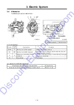
Page 43: ...controller functions at circuit of contact A After engine oil pressure switch is kept ON for 2 seconds engine is brought to emergency stop Engine oil pressure abnormality detecting circuit functions 2...

Page 44: ...re is more than 0 9psi 6 23kPa 0 06bar Always 10 sec Charge A 5 Charge signal disappears and lamp goes on After starting engine 10 sec Emergency Discharge temp H E 1 Thermister Lamp goes on at 248 F 1...

Page 45: ...tart prohibition It goes ON when starter switch is ON Separator receiver tank pressure OFF in case of more than 14 6psi 0 1MPa 1bar ON in case of lower than 7 3psi 0 05MPa 0 5bar 5 Adjustment and insp...

Page 46: ...from actual ones during operation Output voltage of pressure sensor Pressure sensor Regulator secondary pressure psi MPa bar Output voltage DCV 0 0 0 5 21 8 0 15 1 5 1 1 Voltage outputted from emergen...

Page 47: ...by coolant temperature When purge switch is turned ON SV1 functions continuously and it is operated at engine speed of approximately 1 400 min 1 The time when SV1 and SV2 are OFF Coolant temperature...

Page 48: ...e rises over the emergency stop pre determined temperature it makes emergency controller Ry4 relay ON and it sends abnormality signal to ECU to stop engine Emergency stop set temperature 248 F 120 CN2...

Page 49: ...cc terminal Power supply DC5V CN3 6 NIL CN3 7 R B Engine controller ECU CN5 43 terminal It supplies power DC5V to engine controller ECU acceleration sensor circuit CN3 8 R W Engine controller ECU CN5...

Page 50: ...manual regeneration CN19 3 Br B Cleaning exhaust filter lamp DPF cleaning exhaust filter lamp It lights on when automatic regeneration is performed due to accumulation of soot at DPF CN19 4 Br R Rege...

Page 51: ...3 Electric System 3 17 3 3 Engine Controller ECU Part number 46870 64400 PC14021E D i s c o u n t E q u i p m e n t c o m...

Page 52: ...es it for after treatment CN4 13 NIL CN4 14 NIL CN4 15 NIL CN4 16 Y Injector 4 Injects fuel to injector 4 CN4 17 G R Injector 1 Injects fuel to injector 1 CN4 18 NIL CN4 19 W G Intake throttle valve P...
Page 53: ...CN4 41 NIL CN4 42 NIL CN4 43 NIL CN4 44 NIL CN4 45 NIL CN4 46 NIL CN4 47 G O Injector 1 Injects fuel to injector 1 CN4 48 NIL CN4 49 NIL CN4 50 NIL CN4 51 B O Fuel temperature sensor GND terminal Grou...

Page 54: ...supply DC5V CN5 25 Br Regeneration required lamp DPF regeneration required lamp When the soot accumulated on DPF can not be automatically regenerated lamp lights to require regeneration CN5 26 NIL CN5...

Page 55: ...ct No 3 terminal Trouble diagnosis tool connection terminal CAN communication CN5 54 Br EGR valve It operates EGR DC motor and it controls valve lift of EGR valve ECU decides EGR gas volume based on e...

Page 56: ...lay exciting coil Power supply DC12V CN5 74 P B EGR pressure sensor No 4 terminal Grounding CN5 75 O L SA D SMARTASSIST Direct No 2 terminal Trouble diagnosis tool connection terminal CAN communicatio...

Page 57: ...ulated on DPF DPF controller CN19 1 terminal is electrified to light the lamp ON For the details of error trouble diagnosis tool SA D is connected to check them SA D SMARTASSIST Direct See 4 6 Engine...

Page 58: ...tch BR terminal It detects battery voltage and it controls rotor coil electromagnetic current L Y Emergency controller CN2 11 terminal It makes warning lamp go on when battery charging function is abn...

Page 59: ...ontroller CN2 11 terminal Measure voltage of alternator BAT terminal during operation Normal DC13 to 15V Abnormal Battery voltage is same as when stopping Normal DC13 to 15V Abnormal Higher than DC15...

Page 60: ...B Battery terminal For supplying power to starter which enables starter pinion to turn S W Starter relay No 3 terminal For supplying power to make starter pinion to spring out and also a little power...

Page 61: ...magnet switch S terminal Power supply circuit to drive starter pinion 4 B G Engine controller ECU CN5 28 terminal When engine controller ECU senses engine start by charge signal the contact between C...

Page 62: ...resistance at 20 30 10 Contact rating Motor load Halogen lamp load 20A 2 List of functions Pin No Line color Connection Function 1 L R Engine controller ECU CN5 68 terminal Power supply circuit for E...

Page 63: ...9 Engine Oil Pressure Switch for emergency stops YANMAR part number 119761 39450 PC14028 1 Specification Setting pressure 7 1psi 0 049MPa 0 49bar Contact type B contact switch Contact OFF in excess o...

Page 64: ...Part number 44364 08200 PC08033 Note Take care not to tighten excessively Less than 17 7lbf in 2N m 20kgf cm Characteristic of temperature resistance Temperature F Resistance value Permissible value...

Page 65: ...OUT Output Pressure 0psi 0MPa 0bar DC0 5V Pressure 14psi 0 1MPa 1bar DC0 9V Pressure 85psi 0 6MPa 6bar DC2 9V Pressure 100psi 0 69MPa 6 9bar DC3 3V Pressure 142psi 0 98MPa 9 8bar DC4 5V GND Grounding...

Page 66: ...04100 PC08037E 1 Float position Resistance value E 110 0 7 0 1 2 32 5 F 3 0 2 0 3 15 Air filter Differential Pressure Switch Part number 32148 03000 SC10016 Operating pressure 6 2kPa A Contact Warning...

Page 67: ...speed sensor 10 New air temperature sensor 11 Intake air temperature sensor 12 Intake air throttles 13 EGR valve 14 EGR Intake Exhaust pressure sensor 15 EGR gas temperature sensor 16 Exhaust manifold...

Page 68: ...PC14032 3 16 2 Rail A pressure of up to 160MPa is accumulated in the rail The rail is equipped with a rail pressure sensor and it sends information to the ECU In the case of an abnormal increase in t...

Page 69: ...rther take care not to touch any cable at key on because high volt current flows to injector 3 16 5 Water temperature sensor ECU Allows the CSD Cold start device and EGR Exhaust gas recirculation to b...

Page 70: ...am speed sensor is equipped on the gear side Based on these 2 sensor outputs the ECU recognizes the engine speed and each piston position YANMAR part number 129A00 14710 Installation 70 8 4 4lbf in 8...

Page 71: ...side it may have internal damage Do not apply excessive impact or load to the throttle Do not touch the stop screw part as it has already been adjusted Prevent any foreign matter including oil dust an...

Page 72: ...sensor EGR control for reduction of exhaust gas is implemented by EGR Intake Exhaust pressure sensor intake air temperature sensor EGR gas temperature sensor and exhaust manifold temperature sensor P...

Page 73: ...ttle valve for DPF regeneration control For the details of DPF regeneration control refer to 3 1 4 clause PC14046E YANMAR part number 129978 17700 Installation 62 0 12 4lbf in 7 1 4N m 71 14kgf cm Not...

Page 74: ...is installed to the supply pump and the thermistor changes the resistance according to the temperature The resistance is low when the fuel temperature is high and is high when the temperature is low T...

Page 75: ...for failure diagnosis 2 Ask the clients about the trouble in details In order to prevent misunderstanding and incorrect judgment about the trouble it is necessary to ask users or operators about the...

Page 76: ...ouble Even if you have repaired the trouble unless you get rid of the fundamental cause of the trouble it will repeatedly occur Therefore perform full investigation of the trouble and it is absolutely...

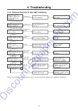
Page 77: ...Battery specific gravity too low or electrolyte short Shortage of fuel Supply fuel Check fuel Not exists Exists Check fuel filter and fuel pre filter Filter element clogging Replace it Normal Cloggin...

Page 78: ...bly Change pressure gauge for replacement one and re adjust pressure gauge Faulty pressure gauge Normal Adjustment Replace it Faulty adjustment Repair or replace it Check function of starting unloader...

Page 79: ...ransported or if any air mixed Fuel feed pump clogging Faulty fuel pipes Clean strainer Repair pipes Bleed air Filter clogging Clean or replace Check adjustment of pressure regulator Clogging is large...

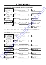
Page 80: ...t by correcting no load revolutions Faulty adjustment Re adjust Adjustment Faulty adjustment It bursts at less pressure Faulty adjustment of pressure Re adjust pressure Adjustment Change pressure gaug...

Page 81: ...el too high Not collection Faulty oil separator Check compressor oil level F Faulty oil seal of compressor air end Disassemble check Replace oil seal No clogging Faulty Check unloader valve function w...

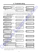
Page 82: ...e A Faulty selection of air compressor Less than 3 000min 1 Filter element clogging Replace it Clogging Check fuel filter and fuel pre filter Check how fuel transported or if any air mixed Faulty fuel...

Page 83: ...ectrically connected Repair or replace it Repair wire connection Trouble of emergency controller Repair or replace it At no load Electrically connected Normal Disconnection or faulty contact between e...

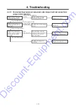
Page 84: ...vice pressure sensor See 3 12 Output voltage normal Replace it Not wire disconnected Repair wire connection Repair or replace it Faulty setting of purge releasing pressure L Trouble of service pressur...

Page 85: ...heck belt tension Tension not acceptable or faulty belt Check compressor oil filter Filter clogging Replace it Proper Faulty Fin tubes much soled Soiled Wash or clean Normal Normal Normal Faulty Adjus...

Page 86: ...Shortage Check engine oil filter Filter clogging Replace it Faulty oil pressure switch Replace it Normal Normal Proper Faulty Check engine oil pressure Faulty of engine lubrication system Repair the...

Page 87: ...ash and clean Normal Normal Normal Faulty Adjust or replace Relocation Check water quantity and quality in radiator More than 104 F 40 Less than 104 F 40 Check radiator fin tubes Faulty sensor Faulty...

Page 88: ...Check fuel pipes Faulty fuel pipes Faulty Repair pipes and bleed air Normal Check function fuel air bleeding electromagnetic pump Faulty fuel air bleeding electromagnetic pump Repair or replace it It...

Page 89: ...t pressure Check and locate pressure maladjustment or defective safety valve In case of malfunction of safety valve safety valve should be replaced F Faulty unloader Faulty seat of unloader valve or f...

Page 90: ...Industries Co Ltd Even disconnection of sensor or its short circuit causes engine to stop N Check and confirm that electrical conductance exists between water temperature sensor emergency controller C...

Page 91: ...amp 1 on monitor panel lights For the details take following procedure to check and confirm engine trouble conditions diagnosis trouble code DTC by connecting trouble diagnosis tool SMARTASSIST Direct...

Page 92: ...nication speed 250k selection ECU address 00 engine selection Select Diagnostic codes Logged DTC from Diagnostics Execution screen Logged DTC Clicking Active failure Action and Probable causes will be...

Page 93: ...e performed by regeneration switch but these forced regenerations can be done optionally By using SA D For the details of regeneration refer to 3 1 4 Procedure Select Active control from Diagnosis Tes...

Page 94: ...ing 4 20 PC14058E Implementing DPF Active Regeneration Press RUN button to proceed regeneration Stopping it press STOP button When regeneration is finished Red lamp goes off D i s c o u n t E q u i p...

Page 95: ...ular location of injector 4 P1146 Injector bank 1 short circuit P0204 Disconnection in a particular location of injector 1 P1149 Injector bank 2 short circuit P0217 Increase in coolant temperature P11...

Page 96: ...g request 1 P1478 ECU shutoff path fault 5 P2452 DPF differential pressure sensor abnormallyhigh pressure P1479 ECU shutoff path fault 6 P2453 DPF differential pressure sensor abnormal learning value...

Page 97: ...ced driving and checking and confirming engine various control values Permit to use SA D is required and certified by engine manufacturer User ID and password are required 1 SA D of the function CAN C...

Page 98: ...necessarily re written and also it is necessary to change Ser No of ECU When replacing injectors correction value should be re written in ECU When replacing the rail ECU should be reset When replacin...

Page 99: ...Y 43540 08800 YANMAR 529A00 55730 Element YANMAR 129A00 55730 O ring element side YANMAR 129A00 55740 O ring drain cap YANMAR 129242 55740 Belt YANMAR 129612 42350 Air control Pressure regulator 36400...

Page 100: ...e sensor 44328 20600 Service pressure sensor 44328 20600 Regulator secondary pressure sensor 44328 20600 Discharge temperature sensor 44364 06500 Water temperature sensor 44364 06500 Engine oil pressu...

Page 101: ...o Parts name 1 Emergency controller 2 Residual pressure start prohibition lamp 3 Engine controller ECU 4 Fuse 20A 5 Fuse 20A 6 Fuse 10A 7 Fuse 80A 8 Glow plug relay 9 Starter relay 10 EGR valve relay...

Page 102: ...text book contains the most recent information available at the time of printing and the contents of the list are based on information in effect at that time and are subject to change without notice...

Page 103: ...ie Terex JLG MultiQuip Mayco Toro Stone Diamond Products Magnum Airman Mustang Power Blanket Nifty Lift Atlas Copco Chicago Pneumatic Allmand Brothers Essick Miller Spreader Skyjack Lull Skytrak Tsuru...

Reviews: