background image

2. Maintenance


2-17 

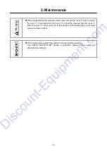
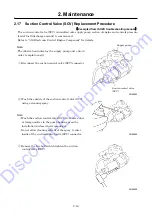
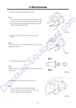
  Pull out the suction control valve (SCV). 


Note: 


If it is hard to pull it out due to the resistance on the 

O-ring, pull it out while rotating it from side to side. 


To prevent foreign matter from entering, do not put 

gloves on from the next work. 


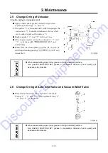
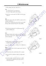
  Remove the O-ring of the suction control valve 

(SCV). 


Note: 

Be careful not to let foreign matter enter the pump 
housing at removal. 


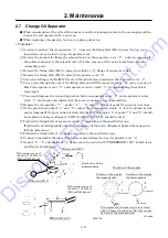
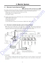
  Check the replacement part. 


Note: 

Make sure that you have got all parts indicated in the 
illustration. 


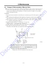
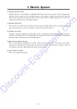
  Place the new O-ring in the O-ring groove. 


Note: 


Do not touch the O-ring with dirty hands. 


Perform this work after making sure there is no 

foreign matter in the O-ring groove. 


SG09046


SG09047


SG09048


SG09049

Discount-Equipment.com

Summary of Contents for PDS400S-6C3

Page 1: ...www discount equipment com D i s c o u n t E q u i p m e n t c o m ...

Page 2: ...nie Terex JLG MultiQuip Mayco Toro Stone Diamond Products Magnum Airman Mustang Power Blanket Nifty Lift Atlas Copco Chicago Pneumatic Allmand Brothers Essick Miller Spreader Skyjack Lull Skytrak Tsurumi Husquvarna Target Whiteman Concrete Mortar Stow Concrete Mortar Baldor Wacker Sakai Snorkel Upright Mi T M Sullair Neal Basic Dynapac MBW Weber Bartell Bennar Newman Haulotte Ditch Runner Blaw Kno...

Page 3: ... we request you to make sure to start the job after clarifying it Service personnel is required to safely take quick and proper countermeasures as well as to use correct technology of maintenance in case of field services and periodical maintenance It is important that service personnel should have proper and sufficient knowledge about the structure and function of the unit and should be well fami...

Page 4: ...ed Pump 2 13 2 10 Supply Grease to Trailer Hub Bearing 2 13 2 11 Supply Grease to Leaf Spring Pin 2 13 2 12 Check and Confirm that the Fixing Bolts for the Drawbar are Properly Tightened 2 13 2 13 Manual Air Bleeding Method for Fuel Line System 2 14 2 14 Clean inside of Fuel Tank 2 14 2 15 Clean Drain Separator Aftercooler type only 2 15 2 16 Values of Various Adjustments of Engine 2 15 2 17 Sucti...

Page 5: ...e sensor 3 39 3 18 12 Barometric pressure sensor 3 40 3 18 13 Intake air temperature IAT sensor 3 40 3 18 14 EGR position sensor 3 41 3 18 15 Boost pressure sensor 3 42 3 18 16 Boost temperature sensor 3 42 4 Troubleshooting 4 1 4 1 Repairing Procedures 4 1 4 1 1 Safety caution 4 1 4 1 2 Caution during failure diagnosis 4 1 4 1 3 How to use the failure diagnosis 4 2 4 2 Failures of Compressor and ...

Page 6: ... Engine RPM drop is displayed abnormality code and engine will stop 4 10 4 4 Others 4 11 4 4 1 Abnormality code is not shown engine will stop 4 11 4 5 Explanation of Trouble Diagnosis 4 12 4 6 Engine Trouble Diagnosis Function 4 14 4 6 1 Engine trouble diagnosis 4 14 4 6 2 How to delete diagnostic trouble codes DTC 4 18 4 6 3 List of diagnostic trouble codes DTC 4 19 4 6 4 Diagnostic service tool ...

Page 7: ... conditions altitude yd m less than 1 640 1 500 Engine Type ISUZU CI 4JJ1XYCD 01 ISUZU CI 4JJ1XYCD 01G Rated output hp min 1 kW min 1 113 2 2 200 84 4 2 200 Fuel consumption g kW h 209 Rated RPM min 1 2 200 RPM at unload conditions min 1 1 300 Net dry mass lb kg 639 290 Lubricating oils Engine oil capacity H L level gal L 3 9 2 9 15 11 Compressor oil capacity including receiver tank and oil cooler...

Page 8: ...ilter clogging psi kPa bar 0 9 6 23 0 0623 Engine air filter clogging psi kPa bar 0 9 6 23 0 0623 Battery abnormality When not charged Discharge air temperature at separator F 239 115 Boost temperature rise F 185 85 Coolant temperature sensor disconnection F Detection of disconnection Set value Pressure control valve psi MPa bar 58 0 40 4 0 Actuating pressure of safety valve psi MPa bar 150 1 03 1...

Page 9: ...1 Specification 1 3 1 3 Outline Drawing PC14064E Unit in D i s c o u n t E q u i p m e n t c o m ...

Page 10: ...1 Specification 1 4 PC14064E Unit mm D i s c o u n t E q u i p m e n t c o m ...

Page 11: ... 16 Fan 5 Pressure sensor 17 Intercooler 6 Pressure regulator 18 Oil cooler 7 Solenoid valve for starting unloader SV2 19 By pass valve 8 Safety valve 20 Exhaust muffler 9 Air filter indicator 21 Alternator 10 Air filter For compressor air end 22 Turbo charger 11 Air end 23 Battery 12 Engine oil filler port Used as oil level gauge 24 Discharge pipe 1 2 3 4 5 6 7 8 9 10 11 12 13 14 15 16 17 18 19 2...

Page 12: ...4 Fuel tank 31 Priming pump 45 Starter 32 Fuel filter 46 Fuel air bleeding electromagnetic pump 33 Coupling 47 Fuel filler cap 34 Vacuator valve For compressor air end 48 Fuel tank drain valve 35 Compressor oil filter 49 Engine oil drain valve 36 Solenoid valve for starting unloader SV1 50 Oil cooler drain valve 37 Valve for low temperature start 51 Radiator drain valve 38 Separator receiver tank ...

Page 13: ...the standard machine are shown in the following figure For the details of the other standard devices refer to page 1 5 1 6 PC13024 PDS400SC 6C3 No Description No Description 1 Aftercooler 3 Drain port of aftercooler 2 Drain separator 4 Drain warming valve 1 2 4 3 D i s c o u n t E q u i p m e n t c o m ...

Page 14: ...ime indication screen is changed by turns as shown above Push Push A120171 Lamp Error code Reset switch When this switch is pushed on while lamp is blinking lighting it shows error code When starter switch is placed to STOP displayed screen is reset Blinking Warning Lighting Emergency Discharge air pressure gauge For indication of working pressure Starter switch For starting and stopping engine En...

Page 15: ...R TEMP AT SEPARATOR A6 When air temperature at the outlet of the separator reaches warning temperature 239 F 115 BOOST TEMP A7 When boost temperature reaches warning temperature 185 F 85 WATER TEMP SENSOR A8 When engine coolant temperature sensor is disconnected Emergency display When any trouble takes place during operation this displays and it stops as an emergency stop When any abnormality happ...

Page 16: ...d the unloader valve can be fully closed at low pressure Thus the load for starting can be reduced SV1 and SV2 solenoid valves operate 30 seconds at the discharge air temperature of higher than 10 and the temperature should be higher than 10 or it operates 120 seconds Engine revolution speed is fixed at 1 600min 1 for the above mentioned operation conditions Load operation So that SV1 and SV2 sole...

Page 17: ...ir end becomes high vacuum and it causes vacuum noise In order to prevent this noise it opens vacuum relief valve to prevent the compressor air end from becoming vacuum Engine revolution speed at unload conditions is operated at 1 600min 1 under less than discharge air temperature less than 60 and when it becomes higher than 60 the speed will be 1 300min 1 Stop Detecting the pressure inside compre...

Page 18: ...1 Specification 1 12 1 7 Piping Diagram Standard type A120194E D i s c o u n t E q u i p m e n t c o m ...

Page 19: ...1 Specification 1 13 Aftercooler type A120195E D i s c o u n t E q u i p m e n t c o m ...

Page 20: ...1 Specification 1 14 1 8 Fuel Piping PC13053E D i s c o u n t E q u i p m e n t c o m ...

Page 21: ...Molybdenum sulfide Paste spray type 2 1 2 Disassembly and reassembly Select such a place for component disassembly where it is enough spacious and shall be dust free Clean also the surroundings of the part or component to be disassembled removing smudge and adhesive matter by washing them Before removing nylon tubes hydraulic hoses and also fuel hoses clean the inside of the machine unit And also ...

Page 22: ... or dirt may cause rust or corrosion If it is unavoidably necessary to stop disassembling job on the way make sure to protect them against rust and dirt After finishing the disassembling job make sure to check the assembled unit for the direction of rotation rotation speed and oil leak At first perform trial operation at so slow speed that it may not cause seizure or overheating D i s c o u n t E ...

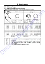
Page 23: ...01 8 68 675 0 47 12 0 87 22 1 194 7 135 1 350 0 63 16 0 94 24 938 1 106 1 055 0 55 14 0 94 24 1 858 4 210 2 100 0 71 18 1 06 27 1 283 2 145 1 450 0 55 14 1 06 27 2 566 4 290 2 900 0 79 20 1 18 30 1 814 2 205 2 050 0 67 17 1 18 30 3 628 3 410 4 100 0 87 22 1 26 32 2 477 9 280 2 800 0 67 17 1 26 32 4 955 8 560 5 600 0 94 24 1 42 36 3 053 1 345 3 450 0 75 19 1 42 36 6 283 2 710 7 100 Applied sections...

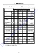
Page 24: ...858 4 210 2100 with spring washer Lifting bail more than M20 10 9 4 8 4 8 1858 4 210 2100 2477 9 280 2800 3053 1 345 3450 with spring washer 5 Pressure vessel and pipes Separator cover 10 9 8 8 221 2 25 245 433 6 49 485 752 2 85 845 1194 7 135 1350 1858 4 210 2100 2477 9 280 2800 3628 3 410 4100 4955 8 560 5600 6283 2 710 7100 with spring washer Pressure control valve body 10 9 8 8 221 2 25 245 43...

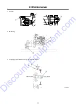
Page 25: ...2 Maintenance 2 5 1 Air end 2 Mounting 3 Coupling portion between comp air end and engine PC12076 ENG SIDE COMP SIDE D i s c o u n t E q u i p m e n t c o m ...

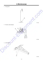
Page 26: ...2 Maintenance 2 6 4 Lifting portion PC13054 5 Pressure vessel and pipes PC13055 6 Undercarriage PC14065 D i s c o u n t E q u i p m e n t c o m ...

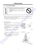
Page 27: ...erhauling or any trouble adjust it in accordance with the following procedures How to adjust regulator Adjust by loosening nut 1 and turning adjusting screw 2 Adjust so that engine speed drops when pressure exceeds the unloader starting pressure 100psi 0 69MPa 6 9bar Make sure to retighten nut 1 after finishing adjustment Turning it to right pressure increases while turning it to left it drops Ple...

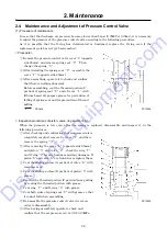
Page 28: ...or prevention of thread galling 65 mm Inspection procedures of piston valve ring and O ring When the pressure is low even after the spring is replaced disassemble and inspect it in the following procedures After checking and confirming that compressed air is completely emptied remove he cover 1 and then remove the spring 3 After removing the cover 4 opposite side 65mm and piston 5 and valve 6 chec...

Page 29: ...d be removed with the cover 1 fitted the cover 4 will jet out by the tensile strength of the inside spring and it could cause a serious accident When reassembling apply thinly grease to O ring and sliding surface Use CALTEX MULTIFAK EP1 grease or equivalent Grease of poor quality will deteriorate the material D i s c o u n t E q u i p m e n t c o m ...

Page 30: ...sassembled degrease it and coat it with liquid sealing packing LOCTITE No 5127 and assemble it When reassembling apply thinly grease to O ring and sliding surface Use CALTEX MULTIFAK EP1 grease or equivalent Grease of poor quality will deteriorate the material 2 6 Change O ring of Auto relief Valve and Vacuum Relief Valve Disassemble and clean the component and check O ring 1 2 and 3 Then replace ...

Page 31: ...hat there are no damages nor abnormalities Replace the oil separator 1 gasket 4 5 and flange of gasket 1 piece by new ones At the point where gasket 4 and 5 contact the oil separator staple 6 is to be pinned in four points diagonally for prevention of static electricity The staples 6 of gasket 4 and 5 should be stapled not being overlapped HD 35 of MAX CO LTD should be used Tighten the fixing bolt...

Page 32: ...to empty compressor oil completely After draining of compressor oil is finished disassemble the by pass valve by removing the bolt 1 and take out the pellet assembly 2 Replace the pellet assembly 2 and O ring 3 by new ones Install O ring 3 coated thinly with compressor oil Supply compressor oil through the filler port provided on the receiver tank Start operation and check the function of by pass ...

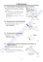
Page 33: ...g grease to the trailer hub bearing contact our office nearby or distributor Grease Chassis grease 2 11 Supply Grease to Leaf Spring Pin Supply grease through grease nipples positioned at the bottom Grease Chassis grease 2 12 Check and Confirm that the Fixing Bolts for the Drawbar are Properly Tightened Check and confirm once every three months that the bolts with which drawbar is fixed are not lo...

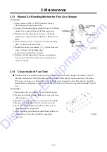
Page 34: ...ean inside of Fuel Tank Condensate is caused and accumulated at the bottom of fuel tank owing to churning of dust or dirt mixed when fuel oil is fed and water drop caused while fuel oil tank is used for a long time When any condensate is found afloat and fuel filter gets clogged too fast fuel oil tank should be cleaned after condensate is removed from fuel oil tank even before the specified cleani...

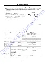
Page 35: ...el ISUZU CI 4JJ1XYCD 01 ISUZU CI 4JJ1XYCD 01G Tightening torque of head bolts lbf in N m kgf cm M11 bolt First stage 620 70 7 1 Second stage 620 70 7 1 Third stage 60 angle tightening Fourth stage 60 angle tightening Valve clearance Air intake in mm 0 006 0 15 in cold season Discharge in mm 0 006 0 15 in cold season Firing order 1 3 4 2 Injection timing BTDC Electronic control unit Nozzle injectio...

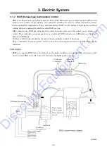
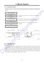
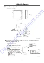
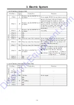
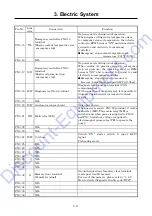
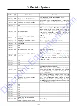
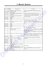
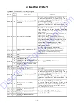
Page 36: ... unit only in order to explain easily Disconnect the suction control valve SCV connector Wash the outside of the suction control valve SCV using a cleaning spray Note Wash the suction control valve SCV to remove dust or foreign matter in the pump housing or on the installation surface when replacing it Do not allow cleaning solvent of the spray to enter inside of the suction control valve SCV conn...

Page 37: ... the O ring of the suction control valve SCV Note Be careful not to let foreign matter enter the pump housing at removal Check the replacement part Note Make sure that you have got all parts indicated in the illustration Place the new O ring in the O ring groove Note Do not touch the O ring with dirty hands Perform this work after making sure there is no foreign matter in the O ring groove SG09046...

Page 38: ...ve SCV installing bolts Note Temporarily tighten the two bolts evenly by hand until the suction control valve SCV contacts the pump housing completely Fully tighten the suction control valve SCV installing bolts to the specified torque 61 to 96lb in 6 9 to 10 8N m 70 to 110kgf cm Note After tightening the two bolts tighten again the bolt tightened firstly Connect the suction control valve SCV conn...

Page 39: ...trol fuel injection system Common rail type ECM engine control module detects such information as engine RPM engine load etc signals from various sensors Base on the information ECM sends electrical signal to supply pump and injectors to properly control fuel injection of each cylinder and injection time in this system PC13089 1 Fuel system Fuel is supplied to supply pump from fuel tank and then s...

Page 40: ...injection amount as a substitute of timer and control of injectors 4 Injection rate control In order to improve combustion in cylinders at first a little fuel is injected pre injection to ignite and then once ignited fuel is injected 2nd time main injection Control of injection timing and injection volume is performed by controlling injectors 5 Maximum fuel injection amount This is calculated by a...

Page 41: ...s cooled and NOX reduction is fulfilled more effectively than usual EGR gas Further cooled intake air density increases and accordingly intake air increases Thus combustion becomes perfect and it causes fuel consumption increase and PM black smoke reduction EGR function ECM is to operate EGR motor according to such engine conditions as engine RPM and engine load and to control EGR valve lift Valve...

Page 42: ...s the engine coolant temperature by signal from engine coolant temperature ECT sensor and changes the period for glow so that the proper starting conditions can be achieved all the time Also after glow function allows to stabilize idling immediately after starting Pressure regulator Accelerator controller Control of output and engine speed Engine controller ECM Electronic control fuel injection sy...

Page 43: ... to adjust engine speed VIEW A Adjusting screw for no load speed Adjusting screw for full load speed 1 Adjust engine speed by turning full load speed adjusting screw Turning the adjusting screw to the right the speed increases and turning to the left it decreases 2 Adjust engine speed at unloaded conditions It is not necessary to adjust the central screw After the adjustment of engine speed is fin...

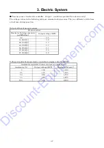
Page 44: ...e sensor No 1 terminal Power supply DC5V for pressure sensor CN6 16 Y W Pressure sensor No 2 terminal Pressure at 2nd stage regulator is detected DC voltage is inputted in accordance with regulator 2nd stage pressure CN6 17 Y G Pressure sensor No 3 terminal Grounding CN6 18 W R Emergency controller No 8 terminal Circuit for sending two kinds of unload speed directives to engine controller ECM 140 ...

Page 45: ... sensor Pressure sensor Regulator 2nd stage pressure psi MPa bar Output voltage DCV 0 0 0 5 14 6 0 1 1 0 9 29 1 0 2 2 1 3 43 7 0 3 3 1 7 58 2 0 4 4 2 1 72 8 0 5 5 2 5 87 3 0 6 6 2 9 Voltage outputted from accelerator controller to engine controller ECM Accelerator controller Control of output and engine speed Accelerator Output voltage DCV Engine RPM min 1 0 1 00 1 300 25 1 75 1 525 50 2 50 1 750 ...

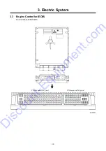
Page 46: ...3 Electric System 3 8 3 3 Engine Controller ECM Part number 44390 03700 SG09037 CN3 terminal 81 pins CN4 terminal 40 pins D i s c o u n t E q u i p m e n t c o m ...

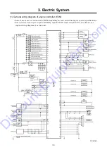
Page 47: ...M Some sensors are not connected to ECM depending on each model having its special specifications Some sensors have input output to ECM by signal of CAN communication For the details see engine wiring diagram of actual unit PC12015E D i s c o u n t E q u i p m e n t c o m ...

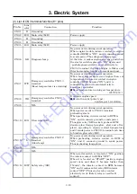
Page 48: ...ature 185 F 85 CN3 8 Y R Emergency controller CN2 8 terminal It outputs engine speed Revolution ratio pulse type 4 pulses per 1 revolution CN3 9 NIL CN3 10 B G Glow relay GR No power exists during usual operation When power is sent to CN3 24 terminal preheating starts When preheating interior contact in ECM is ON and it connects ground to sends power Thus glow relay GR works to preheat ECM decides...

Page 49: ...r than 14 6psi 0 1MPa 1 0bar CN3 18 B W Diagnosis tool No 6 terminal Diagnosis tool connection terminal CAN communication With connection of diagnosis tool it is possible to diagnose engine control system and to check system CN3 19 NIL CN3 20 B W Accelerator sensor shield Noise prevention CN3 21 Y R Main relay MR When power is sent to CN3 24 terminal it works main relay MR Thus main relay MR is sw...

Page 50: ...Emergency controller CN1 3 terminal External input terminal for engine emergency stop When the interior contact RY3 of emergency controller becomes ON all emergency stop signals are sent to ECM to bring engine to emergency stop CN3 48 NIL CN3 49 NIL CN3 50 NIL CN3 51 L W Emergency controller CN1 7 terminal Engine speed signal terminal When the interior contact RY2 of emergency controller becomes O...

Page 51: ...CN3 71 G B Barometric pressure sensor OUT terminal It detects barometric pressure It counts barometric pressure from voltage signal and it corrects fuel injection volume high altitude compensation CN3 72 L R Intake air temperature sensor It detects intake air temperature of unit under operation In order to optimize fuel injection control with ECM it detects intake air temperature at unit in use In...

Page 52: ...cts engine coolant temperature It detects voltage which changes according to resistance and then it counts engine coolant temperature used for emergency stop determination CN4 85 NIL CN4 86 NIL CN4 87 R Cam angle sensor Power supply DC5V for left sensors R Common rail pressure sensor VCC terminal L EGR motor position sensor power supply terminal CN4 88 NIL CN4 89 R B Suction control valve SCV Grou...

Page 53: ...N4 102 NIL CN4 103 W B EGR DC motor V terminal It operates EGR DC motor and it controls valve lift of EGR valve ECM decides EGR gas volume based on engine speed and engine load ratio fuel injection volume and it operates EGR valve by EGR DC motor and also it controls EGR gas volume to be mixed in engine intake air CN4 104 NIL CN4 105 R W Suction control valve SCV When power stays on fuel is sent t...

Page 54: ...power stays on it injects fuel to injector 3 CN4 121 W Injector 1 4 Power supply for injector 1 4 4 Power supply OFF for ECM Power in ECM is not yet OFF 10 seconds after starter switch is OFF In case that it is necessary to switch OFF power supply by clear memory it is necessary that you should wait longer than 10 seconds after switching OFF key switch of power supply 5 Removal of ECM 1 Switch OFF...

Page 55: ...3 Electric System 3 17 3 4 Emergency Controller Part number 46870 56600 PC13068E D i s c o u n t E q u i p m e n t c o m ...

Page 56: ...3 Electric System 3 18 1 Exterior connection drawing PC12069E D i s c o u n t E q u i p m e n t c o m ...

Page 57: ...ncy Discharge temp E E 1 Thermister Lamp lights 248 F 120 Always 1 0 sec Water temp E E 2 Thermister 221 F 105 Always 1 0 sec Eng oil press E 3 Pressure sensor Oil pressure is lower than 14 6psi 0 1MPa 1 0bar Controlled by the engine controller ECM Discharge air temp at separator E E 4 Thermister 248 F 120 Always 1 0 sec Engine speed down E 5 Operation range of 400 1 200min 1 Always 5 seconds afte...

Page 58: ...er switch is ON Discharge air temperature Lower than 50 F 10 When discharge air temp is higher than 50 F 10 or when 120 seconds it becomes OFF Discharge air temperature Higher than 50 F 10 It becomes OFF 30 seconds later RY3 Abnormality output relay OFF during normal operation ON emergency stop RY4 Relay for starting unloader Solenoid valve control It goes ON when starter switch is ON Discharge ai...

Page 59: ...e and sending unit by controller in the following steps 1 Connect resistance to controller as shown right Or use multi speed variable resistance resistance value 1 0kΩ for VRc1 to VRc4 2 Gradually lower resistance values of VRc1 VRc2 and VRc3 and measure them when they reach abnormal values Then check and confirm that they are within the following ranges Item Indicator Set temperature Resistance Ω...

Page 60: ...her than 50 F 10 For 30 seconds CN1 5 B Grounding CN1 6 B Grounding CN1 7 L W Engine controller ECM CN3 51 terminal No power exists during usual operation When starter switch is ON at start and emergency controller CN1 9 terminal voltage is electrified energizing the interior contact RY2 is ON Thus power is sent to engine controller ECM CN3 51 terminal to control engine speed to 1 600min 1 Engine ...

Page 61: ...ter It detects clogging of engine air filter and it enables alarm lamp to blink Differential pressure for warning function More than 0 9psi 6 23kPa 0 06bar CN2 6 B Engine coolant temperature sensor Discharge air temperature sensor Separator discharge air temperature sensor Sending unit Grounding CN2 7 NIL CN2 8 Y R Engine controller ECM CN3 8 terminal It detects 4 pulses per 1 revolution engine sp...

Page 62: ...ller ECM CN3 11 terminal Turn on the preheat lamp CN2 13 W Y Engine controller ECM CN3 7 terminal The flickering the alarm lamp by detecting the abnormal boost temperature Warning set temperature 185 F 85 CN2 14 Y L Engine controller ECM CN3 15 terminal When engine cooling water temperature abnormal signal is detected from ECM CN3 15 terminal the emergency controller interior contact RY3 is made O...

Page 63: ...d by voltage measurement Normal value Measure the battery terminal voltage at full load operation DC28 5 0 5V 3 Check and confirm the following when faulty charging warning lamp lights on Nominal capacity DC24V 50A Measure battery voltage when stopping Recharge battery Abnormality Less than DC24V Normality Repair alternator because it is in trouble Check and confirm charging circuit cable between ...

Page 64: ...ry terminal For supplying power to starter which enables starter pinion to turn S W Starter relay C terminal For supplying power to make starter pinion to spring out and also a little power to make pinion turn for smooth engagement between pinion gear and ring gear when they are in contact Cable connection Voltage DC24V Output 4 0kW D i s c o u n t E q u i p m e n t c o m ...

Page 65: ...er negative pressure SV2 Part number 46811 28700 PC12065 Rated voltage DC24V Function Power is supplied It is ON COM NC OUT IN Opened while electricity is supplied NC IN Rc1 4 OUT Rc1 4 Clip Tube sss y Coil ass y Plunger ass y O ring Return spring Body NO NC COM Opened while electricity is supplied COM NC NC Rc1 4 COM Rc1 4 NO Rc1 4 Diameter of orifice φ4 Diameter of orifice φ2 D i s c o u n t E q...

Page 66: ...tage between is 0 5 0 1V when DC5V is applied between terminals at an atmospheric pressure Pressure and output voltage for reference only Electric wire Signal VCC Power supply DC5V VOUT Output Pressure 0psi 0MPa 0bar DC0 5V Pressure 14psi 0 1MPa 1bar DC0 9V Pressure 85psi 0 6MPa 6bar DC2 9V Pressure 100psi 0 69MPa 6 9bar DC3 3V Pressure 142psi 0 98MPa 9 8bar DC4 5V GND Grounding Operating resistan...

Page 67: ...tance value Ω Permissible value 68 20 11 600 9 176 80 1 300 7 95 35 6 280 8 203 95 840 6 122 50 3 580 7 230 110 560 5 149 65 2 120 7 239 115 490 6 0155 Part number 44364 08200 Characteristic of temperature resistance Temperature F Resistance value Ω Permissible value Temperature F Resistance value Ω Permissible value 68 20 11 620 10 176 80 1 310 6 95 35 6 270 9 203 95 840 5 122 50 3 560 8 230 110 ...

Page 68: ...emark Full tank 46 175 F LED No 8 OFF Green 44 167 LED No 7 OFF Green 40 150 LED No 6 OFF Green 34 127 LED No 5 OFF Green 28 107 1 2 LED No 4 OFF Green 24 89 LED No 3 OFF Green 18 69 LED No 2 OFF Red 14 53 LED No 1 Blinking Red 10 37 E Value when began to consume the fuel F E Float position Resistance value Ω F 3 0 2 0 1 2 32 5 E 110 0 7 0 D i s c o u n t E q u i p m e n t c o m ...

Page 69: ...009 3971 PC12098 3 14 Main Safety Relay MR SR Part number 44324 05800 ISUZU part number 898013 7900 PC12042 Part number of filter ISUZU part number 898071 4010 Rated voltage DC24V Capacity of contact point NO circuit 10A NC circuit 5A Main relay using the NO circuit Safety relay using the NC circuit D i s c o u n t E q u i p m e n t c o m ...

Page 70: ...061 PC12044 3 17 Starter Relay SY Part number 44346 15600 ISUZU part number 898005 6310 PC12045 46 Rated voltage DC24V Capacity of contact point Lamp load 150W Others 12 5A Rated voltage DC24V Rated load Rush current 50A Braking current 30A Coil resistance 100Ω Rated voltage DC24V Rated 30 sec Contact allowable current Instantaneous 200A 30 sec 35A D i s c o u n t E q u i p m e n t c o m ...

Page 71: ...V 12 Boost pressure sensor 4 Fuel temperature FT sensor 13 Boost temperature sensor 5 Engine oil pressure sensor 14 Coolant temperature sensor 6 Crankshaft position CKP sensor 15 Camshaft position CMP sensor 7 Common rail pressure sensor 16 Barometric pressure sensor Mounting on the operation panel 8 Common rail 9 Injector 17 Intake air temperature sensor Mounting on the operation panel 4 5 6 1 1 ...

Page 72: ...supply pump section and controls pressure feed of fuel discharge amount to common rail The engine control module ECM regulates period of electric conduction of suction control valve SCV to regulate the fuel discharge amount Note The connector parts of suction control valve SCV are different in color between 12V and 24V 12V Light gray 24V Light brown PC13091 PC13092 PC13093 Fuel temperature FT sens...

Page 73: ...c If the resistance is low temperature is high the voltage becomes low if the resistance is high temperature is low the voltage becomes high Removal Do not replace the fuel temperature FT sensor If it is faulty replace it as supply pump assembly ISUZU part number 898023 5810 3 18 4 Common rail The common rail receives fuel from supply pump holds the common rail fuel pressure and distributes fuel t...

Page 74: ... converts the pressure into the voltage signal and sends it to ECM Voltage becomes higher as pressure becomes higher and lower as one dose lower ECM calculates the actual common rail pressure fuel pressure based on the voltage signal sent from sensors and uses it for fuel injection control etc Removal Do not replace the common rail pressure sensor If it is damaged replace it as common rail assembl...

Page 75: ... and calculates engine coolant temperature based on change of voltage to use for various controls such as fuel injection and emergency stop decision etc If the resistance is low temperature is high the voltage becomes low if the resistance is high temperature is low the voltage becomes high When coolant temperature rises higher than 221 F 105 warning lamp is made to light on to bring engine to eme...

Page 76: ...position CMP sensor determines the crank angle and uses it to contorl fuel injection and calculate the engine speed These contorls are performed usually based on CKP signal However it is done based on CMP signal if the crankshaft position CKP sensor is faulty Removal Disconnect the connector and remove the 0 4in 10mm mounting bolt and sensor Installation 130 217lbf in 14 7 24 5N m 150 250kgf cm IS...

Page 77: ...0mm mounting bolt and sensor Installation Apply a coat of engine oil to the O ring 69 18lbf in 7 8 2N m 80 20kgf cm ISUZU part number 897312 1081 3 18 11 Engine oil pressure sensor The engine oil pressure sensor is installed near the starter motor of the cylinder block it detects engine oil pressure converts the pressure into the voltage signal and sends it to ECM Voltage becomes higher as pressur...

Page 78: ...essure 5 8psi 40kPa 0 4bar DC1 00V 17 5psi 120kPa 1 2bar DC2 28V SG Grounding Standard atmospheric pressure 1atm 14 7psi 101 3kPa 1 013bar 3 18 13 Intake air temperature IAT sensor The intake air temperature IAT sensor is installed into the operation panel and detects the temperature of intake air for optimum fuel injection control 96 144lbf in 10 8 16 3N m 110 166kgf cm Part number 44364 06600 IS...

Page 79: ...ensor Conector terminal number function Reference value Terminal No Function 1 Position sensor power supply 5V 2 Position sensor W terminal 3 Position sensor V terminal 4 Position sensor U terminal 5 Position sensor GND 6 DC motor W terminal 7 DC motor V terminal 8 DC motor U terminal Note Do not disassemble the EGR position sensor If it is faulty replace it as EGR valve assembly PC12051 SG09072 E...

Page 80: ...l Disconnect the connector and remove the two 0 4in 10mm mounting bolts hoses and sensor Installation 35 53lbf in 4 6N m 40 8 61 2kgf cm ISUZU part number 828139 7750 3 18 16 Boost temperature sensor The boost temperature sensor is installed onto the EGR valve upstream side of intake manifold The sensor is thermistor type The resistance in the sensor changes as the temperature changes Removal Disc...

Page 81: ...s for failure diagnosis 2 Ask the clients about the trouble in details In order to prevent misunderstanding and incorrect judgment about the trouble it is necessary to ask users or operators about the following questions Is there any other disorder than the trouble he has informed Anything abnormal occurred before this trouble Did this trouble happen unexpectedly Or the unit had been operated in b...

Page 82: ...rouble Even if you have repaired the trouble unless you get rid of the fundamental cause of the trouble it will repeatedly occur Therefore perform full investigation of the trouble and it is absolutely necessary to remove the basis of the trouble 4 1 3 How to use the failure diagnosis In the troubleshooting column something abnormal is mentioned in lined parenthesis In the troubleshooting column t...

Page 83: ...o low or electrolyte short or performance degradation Shortage of fuel Supply fuel Check fuel Exists Check fuel pipes Faulty fuel pipes Faulty Check and confirm engine Trouble of engine Repair the trouble and get rid of the cause Abnormality Normality Filter element clogging Replace it Clogging Check fuel filter and fuel pre filter A Not exists Repair pipes and bleed air Normality Faulty adjustmen...

Page 84: ... controller ECM functions well Faulty engine controller ECM or cable connection Replace it or repair connection Check accelerator controller output voltage Engine is in trouble Repair the trouble and get rid of the cause Check how fuel transported or if any air mixed Fuel feed pump clogging Faulty fuel pipes Clean strainer Repair pipes Bleed air Air filter clogging Clean or replace Check adjustmen...

Page 85: ...t safety valve functions at lower pressure than set pressure Faulty pressure gauge Bleed pressure regulator and check for air leak Check orifice at second stage of pressure regulator Disassemble clean or replace parts Orifice clogging Clogging Check if engine controller ECM functions well Faulty engine controller ECM or cable connection Replace it or repair connection Check accelerator controller ...

Page 86: ...too high Separator scavenging orifice clogging Oil separator clogging Check oil level inside separator receiver tank Check silencer at draining portion Clean replace Clean replace Check pipe between aftercooler and silencer Clogging Clean replace Silencer clogging Orifice clogging Clogging in pipes Check drain orifice of aftercooler Clogging Clogging Normality Normality F Faulty oil seal of compre...

Page 87: ...tools Pressure drop and defects of air leaking Late Check that engine speed is at high speed RPM Disassemble clean or replace A Faulty selection of air compressor Oil separator clogging Replace it Check oil separator for clogging Clogging Normality Less than 2 200min 1 Filter element clogging Replace it Clogging Check fuel filter and fuel pre filter Check how fuel transported or if any air mixed F...

Page 88: ...eplace it Unsuitable place of installation Shortage of oil Replenish or replace Check belt tension Tension not acceptable or faulty belt Check compressor oil filter Filter clogging Replace it Proper Faulty Fin tubes much soiled Soiled Wash clean Normality Normality Normality Faulty Adjust or replace Check compressor oil level Faulty sensor Check oil cooler fin tubes Check ambient temperature Short...

Page 89: ... filter Filter clogging Replace it Faulty oil pressure sensor Replace it Normality Normality Proper Clogging Faulty Check engine oil pressure Faulty of engine lubrication system Repair the trouble and get rid of the cause Normal ity Abnormality Less than 7 3psi 0 05MPa Faulty wire connection Faulty Check engine oil pressure sensor J Check wire connection to engine oil pressure sensor K Repair wire...

Page 90: ...just or replace Relocation Check water quantity and quality in radiator More than 104 F 40 Less than 104 F 40 Check radiator and intercooler fin tubes Faulty sensor Abnormality More than 221 F 105 M Check engine coolant temperature ETC sensor N Replace it Check coolant temperature Repair the trouble and get rid of the cause Normality L Faulty emergency controller Normality Replace it 1 O Operation...

Page 91: ...d Normality Check the cable connection to each emergency stop sensor Repair wire connection Check of electric conductance between emergency controller CN1 3 terminal and ground Short circuit Repair wire connection No conduction exists Exists Check of electric conductance between engine controller ECM CN3 1 3 4 terminals and ground Wiring disconnection No conduction exists Repair wire connection Ex...

Page 92: ...t or defective safety valve In case of malfunction of safety valve safety valve should be replaced F Faulty unloader Faulty seat of unloader valve or faulty function of unloader piston Remove unloader assembly from compressor air end and disassemble it for inspection and replace O ring G Check discharge air temperature Check whether actual rise of discharge air temperature stops engine or any fail...

Page 93: ...into voltage signal changes the resistance of the temperature at the thermistor Engine maker supply parts Check and confirm in accordance with the 4 6 Engine Trouble Diagnosis Function Even disconnection of sensor or its short circuit causes engine to stop N Check and confirm that DC voltage exists between emergency controller CN2 14 terminal and ground If power exists between emergency controller...

Page 94: ...rn flash code Procedure Turn starter switch to RUN position and continue pressing diagnosis switch 2 When engine is in trouble it displays trouble conditions with blinking patterns flash code of the diagnosis lamp 1 while diagnosis switch is pressed Example of blinking pattern Flash code SG09079 2E Long interval blinking approx 1 2 seconds Short interval blinking approx 0 3 seconds A120184 1 2 Lon...

Page 95: ...ed such as short circuit with other wiring 15 Crank sensor fault no signal Open circuit in sensor wiring Crank sensor fault signal fault Broken tooth unnecessary signal mixed such as short circuit with other wiring 16 Cam sensor out of phase Camshaft gear crankshaft gear installing angle is out of phase or damage in gear 19 Starter cut relay fault Starter cut relay fault 22 Intake air temperature ...

Page 96: ...cation fault 118 Common rail pressure fault 1st stage Common rail pressure abnormal increase Common rail pressure fault 2nd stage 151 Common rail pressure fault Excessive pressure feed in pump Common rail pressure abnormal increase 158 Injection nozzle common 1 drive system fault Open short circuit in injection common 1 side electrical wiring EDU output part fault 159 Injection nozzle common 2 dri...

Page 97: ... the detailed countermeasures refer to Troubleshooting manual Service manual published by Isuzu Motors If scan tool is fitted it is possible to check or read troubles by scan tool operation Take special care in handling fuel system and so refer to the following cautions Fuel pipes Never use such pipes as used high pressure pipes of fuel system and injector pipes Make sure to replace used ones by n...

Page 98: ...h of the monitor panel Diagnosis switch to maintain is ON by momentary type press and hold Switch ON memory clear switch connection of ECM CN3 32 terminal and ground connection To ground 0 75G terminal female terminal of engine controller ECM of the operation panel inside PC12061E Female terminal Engine controller ECM PC14070 Wait for more than 3 seconds in the ON Switch OFF memory clear switch co...

Page 99: ...rt number 898143 0410 Fuel pre filter ASS Y Isuzu part number 898075 8552 Fuel pre filter element 43543 00900 Isuzu part number 898074 2880 Fuel air bleeding electromagnetic pump repair kit Isuzu part number 898173 1650 Gasket for engine feed pump joint Isuzu part number 109630 0850 3 Copper packing for air bleeding plug of the EGR cooler Isuzu part number 909571 4100 Belt Isuzu part number 898038...

Page 100: ...R 44346 15500 Isuzu part number 894460 7061 Electromagnetic pump relay FR 44346 07500 Isuzu part number 582550 0300 Electromagnetic pump 43650 02500 Isuzu part number 898009 3971 Solenoid valve for starting unloader SV1 46811 27100 Solenoid valve for starting unloader SV2 46811 28700 Fuse 10A 46934 03200 2 Fuse 60A 44470 02300 2 Pressure sensor 44328 20600 Barometric pressure sensor 44328 21500 Is...

Page 101: ...5 3 5 2 Engine Wiring Diagram PC13087E PC13088 D i s c o u n t E q u i p m e n t c o m ...

Page 102: ...d HOKUETSU INDUSTRIES CO LTD This text book contains the most recent information available at the time of printing and the contents of the list are based on information in effect at that time and are subject to change without notice www discount equipment com D i s c o u n t E q u i p m e n t c o m ...
Reviews: