3. Electric System
3-6
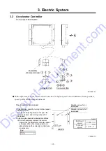
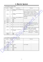
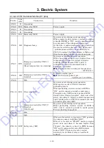
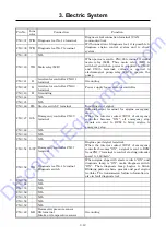
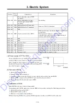
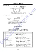
1. List of functions (Connector CN6)
Pin Name
Line
color
Connection Function
Connector
CN6-9 R
Engine controller (ECM) No.42
terminal
Power supply (DC5V) for accelerator sensor.
CN6-10 W
Engine controller (ECM) No.63
terminal
Based on the input voltage of CN6-16
terminal, change the resistance between
CN6-10 and CN6-11 and then output it to
engine controller. (According to the pressure
of regulator secondary side, adjust the
opening and closing degree of engine
accelerator.)
CN6-11 B
Engine controller (ECM) No.41
terminal
Grounding
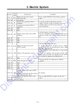
CN6-12
-
NIL
-
CN6-13
-
NIL
-
CN6-14
-
NIL
-
CN6-15
Y/R Pressure sensor No.1 terminal Power supply (DC5V) for pressure sensor.
CN6-16
Y/W Pressure sensor No.2 terminal
Pressure at 2nd stage regulator is detected.
(DC voltage is inputted, in accordance with
regulator 2nd stage pressure.)
CN6-17
Y/G Pressure sensor No.3 terminal Grounding
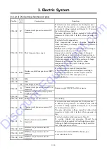
CN6-18 W/R
Emergency controller No.8
terminal
Circuit for sending two kinds of unload speed
directives to engine controller (ECM).
●
140°F(60
℃
) less than the discharge
air temperature 1,600min
-1
●
140°F(60
℃
) higher than the discharge air
temperature 1,300min
-1
CN6-19
-
NIL
-
CN6-20
-
NIL
-
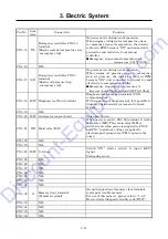
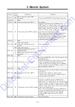
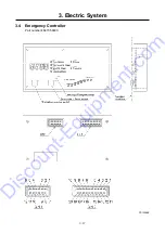
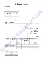
2. List of functions (Terminal A, Connector CN5)
Pin Name
Line
color
Connection
Function
Te
rm
inal
A
(Female
terminal)
-
NIL
-
Connector
CN5-3
R/W 10A fuse
Power supply
CN5-4
-
NIL
-
CN5-5
-
NIL
-
CN5-6 B
Grounding
-
CN5-7
-
NIL
-
CN5-8
-
NIL
-
Discount-Equipment.com
Summary of Contents for PDS400S-6C3
Page 1: ...www discount equipment com D i s c o u n t E q u i p m e n t c o m ...
Page 10: ...1 Specification 1 4 PC14064E Unit mm D i s c o u n t E q u i p m e n t c o m ...
Page 19: ...1 Specification 1 13 Aftercooler type A120195E D i s c o u n t E q u i p m e n t c o m ...
Page 20: ...1 Specification 1 14 1 8 Fuel Piping PC13053E D i s c o u n t E q u i p m e n t c o m ...
Page 101: ...5 3 5 2 Engine Wiring Diagram PC13087E PC13088 D i s c o u n t E q u i p m e n t c o m ...

