3. Electric System
3-12
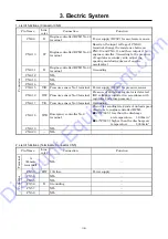
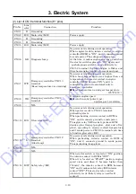
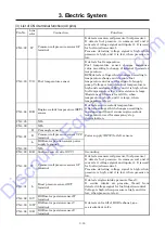
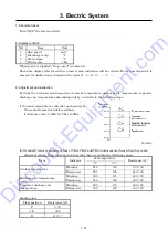
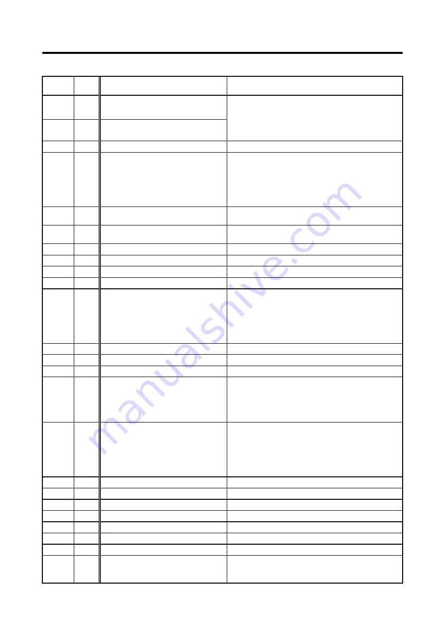
Pin No. Line
color
Connection Function
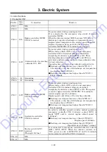
CN3-37 W/B Diagnosis tool No.14 terminal
Diagnosis tool connection terminal (CAN
communication)
With connection of diagnosis tool, it is possible to
diagnose engine control system and to check
system.
CN3-38 W/G Diagnosis tool No.7 terminal
CN3-39
-
NIL
CN3-40 Y/R Main relay (MR)
When power is sent to CN3-24 terminal, it works
main relay (MR). Thus main relay (MR) is
switched and when power is supplied to CN3-2
and CN3-5 terminal, voltage is applied to
electromagnet pump relay (FR) to operate the
pump.
CN3-41 B Accelerator controller CN6-11
terminal
Grounding
CN3-42 R Accelerator controller CN6-9
terminal
Power supply for accelerator controller.
CN3-43 B Grounding
CN3-44
-
NIL
CN3-45
-
NIL
CN3-46 R/L Starter switch C terminal
Inputting start signal.
CN3-47 G/L Emergency controller CN1-3
terminal
External input terminal for engine emergency
stop.
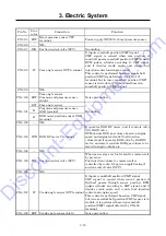
When the interior contact (RY3) of emergency
controller becomes “ON”, all emergency stop
signals are sent to ECM to bring engine to
emergency stop.
CN3-48
-
NIL
CN3-49
-
NIL
CN3-50
-
NIL
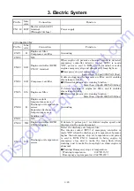
CN3-51 L/W Emergency controller CN1-7
terminal
Engine speed signal terminal.
When the interior contact (RY2) of emergency
controller becomes “ON”, a signal is sent to ECM
from CN1-7 terminal to control starting unloader
speed to 1,600min
-1
.
CN3-52 Y/B Diagnosis tool No.1 terminal
Diagnosis switch
When engine stops with starter switch “ON”, and
diagnosis lamp is “ON”, make diagnosis switch
“ON”. Then diagnosis lamp begins to blink.
Blinking pattern shows present and past engine
troubles. The transmission failure information is
also in fault diagnosis tool.
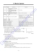
CN3-53
-
NIL
CN3-54
-
NIL
CN3-55
-
NIL
CN3-56
-
NIL
CN3-57
-
NIL
CN3-58
-
NIL
CN3-59
-
NIL
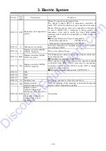
CN3-60 L/B
Barometric pressure sensor
SG terminal
Intake air temperature sensor
Grounding
Discount-Equipment.com
Summary of Contents for PDS400S-6C3
Page 1: ...www discount equipment com D i s c o u n t E q u i p m e n t c o m ...
Page 10: ...1 Specification 1 4 PC14064E Unit mm D i s c o u n t E q u i p m e n t c o m ...
Page 19: ...1 Specification 1 13 Aftercooler type A120195E D i s c o u n t E q u i p m e n t c o m ...
Page 20: ...1 Specification 1 14 1 8 Fuel Piping PC13053E D i s c o u n t E q u i p m e n t c o m ...
Page 101: ...5 3 5 2 Engine Wiring Diagram PC13087E PC13088 D i s c o u n t E q u i p m e n t c o m ...

