background image

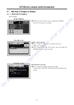
4


Failure cause and measures


4-2 

4.1.2


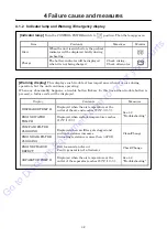
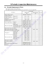
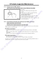
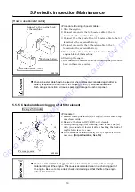
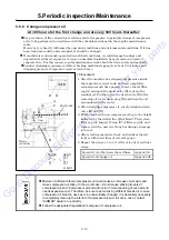
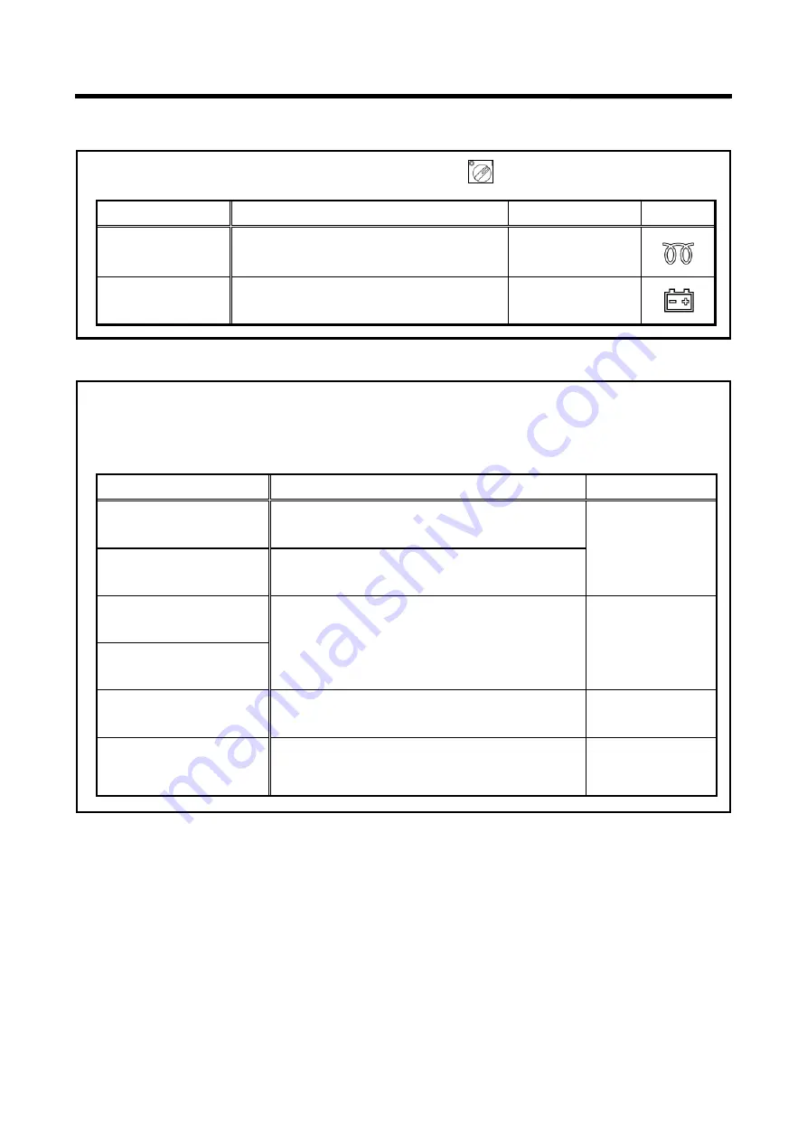
Indicator lamp and Warning / Emergency display 


[Indicator lamp]


Turn the CONTROL POWER switch to 

  position. Then the lamp goes on. 


Item Contents 

Measures 

Monitor 

Glow 

When the unit is switched on, the preheat 

indicator will be displayed briefly during 

preheating. 


Charge 

The battery indicator will be displayed 

when it is not being charged. 

Check wiring. 

Check alternator.


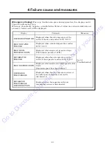
[Warning d isplay]


This displays such trouble of less importance when it occurs during 

operation, but the unit continues operating. 

When any abnormality happens, a trouble button flickers. In this time when trouble button is 

pressed, a failure code will be displayed. 


Display

 Contents 

Measures 

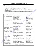
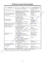
DISCHARGE TEMP.H 

Displayed when the air temperature at the 
outlet of the air-end reaches 

239°F (115

)

See 4.2 

“Troubleshooting” 

ENGINE WATER 
TEMP.H 

Displayed when coolant temperature reaches 

212°F (100

)

.


COMP.AIR FILTER 
CLOGGING 

D

isplayed when air filter gets clogged and 

suction resistance increases. 

[Actuating resistance is more than 

0.9PSI.

]


Clean/Change


ENGINE AIR FILTER 
CLOGGING 

ENGINE CHARGE 
DEFECT 

Belt loosened and/or cut 

Faulty generation of alternator


Check/Change 

SEPARATOR TEMP.H 

Displayed when the air temperature at the 
outlet of the separator reaches 

239°F (115

)

See 4.2 

“Troubleshooting”


Go 

to 

Discount-Equipment.com 

to 

order 

your 

parts

Summary of Contents for PDS400S-6E1

Page 1: ...www discount equipment com G o to D iscount Equipm ent com to order your parts...

Page 2: ...e needs We sell worldwide for the brands Genie Terex JLG MultiQuip Mikasa Essick Whiteman Mayco Toro Stone Diamond Products Generac Magnum Airman Haulotte Barreto Power Blanket Nifty Lift Atlas Copco...

Page 3: ...owing the Machine 2 2 2 3 Installation conditions 2 3 3 Operation 3 1 3 1 Instrument Panel 3 1 3 2 Lubricating oil Coolant Fuel DEF 3 2 3 3 Check before starting unit 3 5 3 4 Operating Procedure 3 12...

Page 4: ...t in death or serious injury CAUTION indicates a potentially hazardous situation which if not avoided may result in minor or moderate injury It may also be used to alert against unsafe practices IMPOR...

Page 5: ...te stamped with the model and serial number is attached to side of the machine Each illustrated figure Fig has a number for instance A130375 at the right bottom This number is not a part number but it...

Page 6: ...g labels are attached to the machine When they are found damaged or peeled off order them from our office nearby or distributor and attach them again 1 2 3 4 5 6 8 9 10 11 12 13 14 15 16 7 G o to D is...

Page 7: ...position of safety warning labels is as follows A180276E 7 6 5 2 3 4 12 13 14 15 8 9 1 16 Receiver tank portion sticking position Shroud portion sticking position 11 10 G o to D iscount Equipm ent co...

Page 8: ...ised functions may be deteriorated or the machine life may be shortened Never use the machine for the purpose of compression of gases other than air or as a vacuum pump Otherwise serious accidents may...

Page 9: ...te liquid from the machine contains harmful material Do not discharge it onto the ground or into the river lake or sea Such material will contaminate the environment Be sure to use a container to hold...

Page 10: ...evel and supplying it 9 Compressor oil filter For filtering compressor oil in the system 10 By pass valve For keeping compressor oil at optimum temperature in the system 11 Oil cooler For cooling comp...

Page 11: ...load For reducing load at start up 27 Pressure control valve For keeping the pressure in receiver tank constantly higher than a certain level in the system 28 Compressor air end For compressing air in...

Page 12: ...pressure regulator Pressure regulator used to control air pressure during low pressure operation 28 Solenoid valve for starting unload For reducing load at start up 29 Pressure control valve For keepi...

Page 13: ...1 2 No Description Function 1 Drain separator For separating water from compressed air cooled through after cooler 2 After cooler For cooling compressed air 3 Drain port of air pipe For draining conde...

Page 14: ...ght of the machine by referring to the values shown in Chapter 7 Specifications of the manual 4 Any crane operations must be performed by a qualified crane operator 2 1 2 Mounting the machine on the t...

Page 15: ...isconnection may not occur while the machine is being towed Make sure if there is no deform or damage on the drawing vehicle and the drawbar of the machine Be sure to keep your hand or finger away fro...

Page 16: ...er one Also a machine has to be installed in the environment where fresh air is always available Keep enough space around the machine for inspection and maintenance access Exhaust gas from the engine...

Page 17: ...hose involved in construction work from entering the construction site or from accessing the machine 2 3 1 Service valve A160694 A160751 1 Installation notes Placing safety fence in position A120199 S...

Page 18: ...often used Do not operate the machine with service valves and relief valve open unless air hoses and or pipes are connected High pressurized air blows out and its air pressure could cause injury to t...

Page 19: ...operate safely A180427 START button Start operation by holding the button for 1 second CONTROL POWER switch Switch to start and stop the unit Switch to change high pressure mode and low pressure mode...

Page 20: ...e sure to use recommended oil listed below Even continuous oil replenishment cannot improve its deteriorated condition Be sure to change the oil completely at every scheduled interval Maker Brand MOBI...

Page 21: ...n 60 it may decrease its antifreezing effect Mixing ratio of LLC antifreeze reference Outside temperature F 5 4 13 22 31 40 49 Outside temperature 15 20 25 30 35 40 45 Mixing ratio 30 35 40 45 50 55 6...

Page 22: ...ty of DEF is not within specification contact the DEF supplier for assistance with disposal Do not dump substantial quantities of DEF onto the ground or send DEF to wastewater treatment facilities Avo...

Page 23: ...e before checking the oil level Procedure 1 Pull out the oil level gauge and wipe it with a clean cloth 2 Then re insert the oil level gauge fully and pull it out again If the oil level gauge shows th...

Page 24: ...emoving radiator cap unfasten it to decrease internal pressure while unlocking first step After checking internal pressure decreased unfasten the radiator cap more until second step unlocked If you fa...

Page 25: ...ng out could cause burning or serious injury to persons nearby 3 3 4 Drain separator receiver tank Gradually opening the drain valve 2 fitted under the separator receiver tank 1 as shown in the fig dr...

Page 26: ...he fuel is extremely flammable and dangerous Be careful of fire because it is very likely to catch fire Refuel only after stopping the engine and never leave open fuel can near the machine Do not spil...

Page 27: ...the engine may stall when opening service valve due to output restrictions If DEF tank level is at 0 the ENGINE STOP indicator will be displayed and the engine will shut down Refill DEF to restore Wh...

Page 28: ...Check each wiring for any loose connection damage to insulating sheathed portion disconnection and short circuit 3 3 10 Check piping of each part Check each piping for any loose connection and also c...

Page 29: ...cable from the battery If the machine is running it might catch the operator s hand into the belts and this could cause a serious injury Be sure to stop the engine and remove the starter key whenever...

Page 30: ...ine The starter switch will stop itself automatically after 15 seconds Wait at least one minute for any subsequent starting operation otherwise the starter motor may overheat and become damaged See 3...

Page 31: ...ss air hoses and or pipes are connected High pressurized air blows out and its air pressure could cause injury to the people nearby When the machine has to be unavoidably temporarily operated with its...

Page 32: ...ing pressure PDSF330DP DPC 6E1 Set the PRESSURE SELECT switch A to the LOW position for 100PSI and the HIGH position for 150PSI You can alternate the usage pressure during operation A180427 A G o to D...

Page 33: ...d will be increase to increase air delivery when pressure is low About AIR BOOSTING MODE When using air boosting mode air delivery will be increased by higher engine speed when the pressure is low The...

Page 34: ...Clogging of fuel filter Discharge of battery Low cranking speed If you do starting manipulation successively the starter will not stop fully and it causes damages to pinion ring gear and breakdown of...

Page 35: ...ne can be easily discovered and preventive measures can be taken Do not open the valves below listed when operating Separator receiver tank drain valve Coolant drain valve Engine oil drain valve Oil c...

Page 36: ...d relieved to atmosphere continuously through the auto relief valve Further when re starting operation next time compressed air will be jetted out through air valves A180437 3 4 8 Air bleeding in fuel...

Page 37: ...istributor because technical knowledge is required A180441 3 5 2 Drain warmer valve The valve 2 is installed for drain antifreezing when discharging water separated at drain separator 3 Be sure to use...

Page 38: ...re air to meet your use View from separator maintenance cover A150855 Service air Operation Low temperature air Normal temperature air 3 way switching valve After cooler 3 way switching valve Drain se...

Page 39: ...Operation 3 21 3 6 SETTING screen Operating condition running parameters and various other settings and be can be read and changed here HOME SCREEN G o to D iscount Equipm ent com to order your parts...

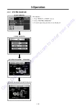
Page 40: ...M Procedure 1 Press HOME on MAIN screen 2 Select SYSTEM DIAGRAM 3 Current operating parameters are displayed MAIN SCREEN SYSTEM DIAGRAM 1 ENGINE HOME SCREEN SYSTEM DIAGRAM 2 COMPRESSOR G o to D iscoun...

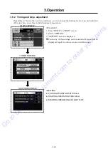
Page 41: ...mperature Procedure 1 Press HOME on MAIN screen 2 Select SETTING 3 SETTING screen is displayed Touch any of the settings and a numerical keypad will be displayed Input the values required within range...

Page 42: ...MAINTENANCE screen is displayed 3 Press NEXT to show engine items 4 Touching any value will display a number pad 5 Touching any value will display a number pad No maintenance alarm will be displayed i...

Page 43: ...ct TREND GRAPH on HOME screen to show TREND GRAPH screen Sampling interval is every 2 seconds log time is up to 40 minutes Press NEXT to show graphs of each items MAIN SCREEN HOME SCREEN TREND GRAPH 1...

Page 44: ...gases reach temperatures hot enough to cause burns to people or ignite and melt other materials During regeneration the area above and immediately surrounding the engine should be free of any possibl...

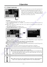
Page 45: ...egeneration High Exhaust System Temperature HEST indicator A will be ON It is normal for engine speed to vary while performing a manual regeneration Regeneration will take anywhere from 15 to 30 minut...

Page 46: ...the emergency stop button After emergency stopping be sure to carry out an investigation of the cause you made stop and the countermeasure release emergency stop button after making sure the safety wa...

Page 47: ...utton blinking Press comp to display more detail on the error Refer to 4 2 and 4 3 After clearing the cause of the error press and hold the RESET button to clear the alert ENGINE button blinking Press...

Page 48: ...le button flickers In this time when trouble button is pressed a failure code will be displayed Display Contents Measures DISCHARGE TEMP H Displayed when the air temperature at the outlet of the air e...

Page 49: ...P HH Displayed when coolant temperature reaches 221 F 105 ENGINE OIL PRESSURE DOWN Displayed when engine oil pressure drops The function pressure 14PSI SEPARRATOR TEMP HH Displayed when the air temper...

Page 50: ...ating and become unable to keep running Press the indicator A to see cause of the failure When DEF Level blinks refill DEF and confirm the lamp is inactive When DEF Quality blinks replace DEF When the...

Page 51: ...logging of the unloader orifice 3 Trouble of emergency controller 4 Engine trouble 5 Fuel filter clogging Call your nearest dealer Disassemble Clean Call your nearest dealer Call your nearest dealer D...

Page 52: ...Change Repair Change High separator temp shutdown 1 Oil cooler clogging 2 Oil filter clogging 3 The discharge air temperature sensor is defective 4 Loosened or disconnected wiring or connector 5 Belt...

Page 53: ...aust manifold exhaust pipe muffler radiator oil cooler air end pipe separator receiver tank and discharging pipe are especially hot so never touch those parts because it could cause serious burns Remo...

Page 54: ...ponds and sea It contaminates the environment When draining waste fluid from machines use leak proof containers to hold such fluids from machine Be sure to follow the designated regulations when dispo...

Page 55: ...onsumable parts of vacuum relief valve 5 19 Performance check of pressure control valve 5 20 Check and change O ring and piston of pressure control valve 5 20 Change rubber coupling 5 21 Change oil se...

Page 56: ...element 5 12 Clean of element in sedimenter 5 13 Check for crack and leak on the exhaust flexible pipe 5 14 Clean inside of radiator 5 13 Clean outside of the radiator 5 14 Change coolant 5 16 Clean...

Page 57: ...ring KUBOTA 16541 43330 1 Element in sedimenter Element E KUBOTA RD451 51940 1 O ring F For element KUBOTA 04817 00160 1 O ring G For body KUBOTA RD451 51930 1 Solenoid valve for starting unload 4681...

Page 58: ...he dipstick shows the oil level between LOW and HIGH it is normal 5 As you finish refilling make sure to close filler port C and to firmly reinsert oil level gauge D A150809 After stopping the engine...

Page 59: ...ery 500 hours If there seems to be a problem in starting an engine due to a flat battery carry out the checks by following the procedures below Ordinary type battery Check battery electrolyte level an...

Page 60: ...th large amount of water immediately If the battery electrolyte gets into your eyes wash it away immediately with plenty of water and see a doctor at once because it is feared that eyesight might be l...

Page 61: ...ill cause spark and damage to each component 5 5 5 Check and clean clogging of air filter element Every 250 hours Procedure 1 Loosen the cap fix latch B at cap A then remove cap and clean inside 2 Rem...

Page 62: ...rain valve E after removing oil cooler drain plug D and drain the oil accumulated in the cooler 2 After draining compressor oil surely retighten drain valve B and E 3 Fill the tank with new compressor...

Page 63: ...sure to use genuine parts 5 5 8 Change air filter element Every 500 hours Be sure to use genuine air filter element Procedure 1 Loosen the cap fix latch B at cap A then remove cap and clean inside 2...

Page 64: ...re filter element Every 500 hours Procedure 1 Remove the filter element A using a filter wrench 2 Spread a thin film of oil on a packing B of a new filter and screw it in For part number See 5 4 3 Aft...

Page 65: ...er See 5 4 7 After finishing clean assemble it in reverse procedure If air remains in the fuel line set the CONTROL POWER switch to position and release the air by loosening bolt H Drain the condensat...

Page 66: ...belt 5 5 14 Clean outside of the radiator oil cooler Every 1 000 hours When the fin tubes diaphragm 1 of a radiator and an oil cooler are clogged with dust or other foreign materials the heat exchang...

Page 67: ...pressure washer in order to protect the fin tubes from being damaged 5 5 16 Check and clean drain outlet port of after cooler After cooler type Every 1 000 hours See 3 5 1 for after cooler drain When...

Page 68: ...op it Then check the coolant level again and replenish if it is short A180194 When removing radiator cap unfasten it to decrease internal pressure while unlocking first step After checking internal pr...

Page 69: ...Make sure to use our genuine parts for replacement Procedure 1 In order to pull out the separator remove the bolts 4 pieces fixing the top cover on the separator cover 2 Remove nylon tubes and copper...

Page 70: ...it requires expert technical knowledge 5 5 23 Change rubber hose 2 000 hours or every 2 years Check hoses used for oil piping for any crack or tear and replace when an abnormality is found When replac...

Page 71: ...es expert technical knowledge 5 5 28 Check and change the unloader bushing 3 000 hours or every 3 years Replace unloader when malfunction occurred even if before normal replace timing When replacing i...

Page 72: ...expert technical knowledge When reassembling apply sufficient grease to O ring Slot O ring and sliding surface Use CALTEX MULTIFAK EP1 grease or equivalent Grease of poor quality will deteriorate the...

Page 73: ...echnical knowledge 5 5 35 Change oil seal bearing Every 12 000 hours When replacing it contact directly us or distributor because it requires expert technical knowledge 5 5 36 Change solenoid valve Ev...

Page 74: ...o clean its inside After running it for a while drain it again 2 Completely charge the battery and disconnect grounding wires Remove the battery from the machine if possible and store it in a dry plac...

Page 75: ...acity L 40 ENGINE Model KUBOTA V3800TIEF4B COHE 1 Type 4 Cycle water cooled direct injection Turbocharged EGR DPF SCR Cylinder quantity Cylinder diameter Cylinder stroke mm 4 100mm 120mm Total displac...

Page 76: ...capacity L 40 ENGINE Model KUBOTA V3800TIEF4B COHE 1 Type 4 Cycle water cooled direct injection Turbocharged EGR DPF SCR Cylinder quantity Cylinder diameter Cylinder stroke mm 4 100mm 120mm Total dis...

Page 77: ...7 Specifications 7 3 7 2 Outline drawing PDS400S 6E1 PDSF330DP 6E1 A180449E G o to D iscount Equipm ent com to order your parts...

Page 78: ...7 Specifications 7 4 PDS400SC 6E1 After cooler type PDS330DPC 6E1 After cooler type A180450E G o to D iscount Equipm ent com to order your parts...

Page 79: ...7 Specifications 7 5 7 3 Wiring Diagram A180195E 1 G o to D iscount Equipm ent com to order your parts...

Page 80: ...7 Specifications 7 6 A180196E 1 G o to D iscount Equipm ent com to order your parts...

Page 81: ...7 Specifications 7 7 7 4 Piping Diagram 7 4 1 Compression air Compressor oil PDS400S 6E1 A180443E G o to D iscount Equipm ent com to order your parts...

Page 82: ...7 Specifications 7 8 PDSF330DP 6E1 A180444E G o to D iscount Equipm ent com to order your parts...

Page 83: ...7 Specifications 7 9 PDS400SC 6E1 After cooler type A180445E G o to D iscount Equipm ent com to order your parts...

Page 84: ...7 Specifications 7 10 PDSF330DPC 6E1 After cooler type A180447E G o to D iscount Equipm ent com to order your parts...

Page 85: ...7 Specifications 7 11 7 4 2 Fuel Piping A180470E G o to D iscount Equipm ent com to order your parts...

Page 86: ...OIL SUPPLY L REMARKS INSPECTION PART CHANGE HISTORY ETC RATED RPM rpm min 1 DISCHARGE AIR PRESS psi OPERATION LOG OPERATION DATE OPERATION TIME AMBIENT TEMP F ENG OIL REPLACEMENT HOUR h TOTAL OPERATIO...

Page 87: ...e needs We sell worldwide for the brands Genie Terex JLG MultiQuip Mikasa Essick Whiteman Mayco Toro Stone Diamond Products Generac Magnum Airman Haulotte Barreto Power Blanket Nifty Lift Atlas Copco...

Page 88: ...Curtis Gehl Pavers Heli Honda ICS PowerGrit IHI Partner Imer Clipper MMD Koshin Rice CH E General Equip ment Amida Coleman NAC Gradall Square Shooter Kent Stanley Tamco Toku Hatz Kohler Robin Wiscons...

Page 89: ...00 99830 Printed DEC 2018 Copyright C 2018 HOKUETSU INDUSTRIES CO LTD All Rights Reserved AIRMAN HOKUETSU INDUSTRIES CO LTD www discount equipment com G o to D iscount Equipm ent com to order your par...

Reviews: