background image

3. Installation


3

-

1

3.1  Transportation 


When loading and unloading unit, be sure to use the lifting bail provided on the center of the unit top.


Never get under the unit which is suspended, because it is very dangerous.


When unit is transferred or moved from working site, be sure to place it on truck bed, and fasten it by 

ropes at the front and rear hooks.


Be sure to put one set of chocks to fix its wheels firmly on the truck bed.Never lift unit which is still in 

operation, or it could cause critical damage to each component or lead to serious accident.


3.1.1


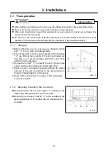
Lifting up 

① 

Before lifting the unit up, make sure to check the lifting 
bail 

2 for any crack and loosened bolts. 

② 

Connect the hook 1 of the crane or shackle with lifting bail 

2 eye fitted at the top center of the unit, and make sure 

that there is no person standing around the unit. Then 
perform hoisting operation. 

③ 

Use auxiliary ropes 3 to prevent the unit from swinging 
and/or twisting, giving signs and signals each other. 

④ 

Select a truck or a crane with capacity sufficient for weight 
and size of the unit by referring to the values shown in 
Chapter 8 “Specifications“ of the manual. 

⑤ 

Never lift the unit while it is running, or this could cause 
a serious accident. 


3.1.2


Mounting the unit on the truck bed   


Be  sure  to  fasten  the  unit  with  ropes 1 as shown in the 
figure right, and securely fix it on the truck bed.   


Be sure to put one set of chocks 2 to the wheels.pull the 
parking brake lever it firmly after the unit is loaded on the 
truck bed. 


A030117


A010190


1

1        2        2        1 

Transportation

Summary of Contents for PDSE900S-4B1

Page 1: ......

Page 2: ...and safety of the engine see the Engine Operation Manual Keep the manual available at all times for the operator or safety supervisor If the manual is lost or damaged place an order with your dealer...

Page 3: ...ck before Starting Unit 4 6 4 5 Unit Operation 4 12 4 6 Stopping Procedures 4 16 5 Periodic Inspection Maintenance 5 1 5 1 Important Items as Periodic Inspection and Maintenance or after Maintenance 5...

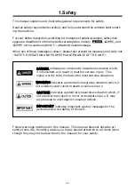
Page 4: ...ently hazardous situation which if not avoided will result in death or serious injury This signal word is to be limited to the most extreme situations WARNING indicates a potentially hazardous situati...

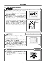
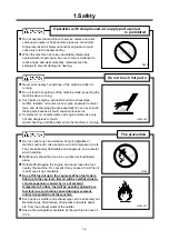
Page 5: ...such pneumatic engineering method or pneumatic caisson method Read each instruction plate which is displayed in the manual or on the unit carefully understand its content and follow the indications t...

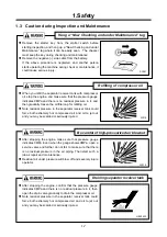
Page 6: ...ion and during operation If the connection part is loosening there is a possibility of piping or a hose separating and getting seriously injured Please remove after closing a service valve and extract...

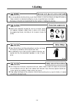
Page 7: ...nts of work for safety TR0085 Safety fittings Have first aid boxes and fire extinguishers near the unit ready for emergency situations such as injuries and a fire It is advisable to have a list of pho...

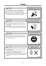
Page 8: ...e Coolant drain valve and plug Engine oil drain valve Oil cooler drain valve Never blow compressed air directly at people Scattered impurities dust or foreign objects in the compressed air may cause s...

Page 9: ...d checking or refilling them while the machine is running Do not under any circumstance bring lit cigarettes or matches near such oils as engine oil and compressor oil etc They are extremely flammable...

Page 10: ...could force both extremely hot compressed air and oil to jet out and you may be scalded or seriously injured After stopping the engine make sure that pressure gauge indicates 0MPa Even when the gauge...

Page 11: ...fan is rotating it may catch the operator or part of his body into the fan and it could cause a serious injury When cleaning dust accumulated in such devices as the air filter by blowing compressed ai...

Page 12: ...urized blows off and it can cause burning Be sure to perform the periodical check of compressor oil and oil separator Neglecting checks could cause overheat of the oil resulting in a fire Waste liquid...

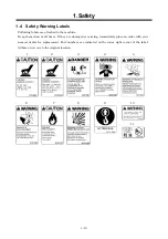
Page 13: ...the machine Keep them clean at all times If they are damaged or missing immediately place an order with your nearest dealer for replacement Part numbers are indicated on the lower right corner of the...

Page 14: ...1 Safety 1 11 The pasting position of safe warning label is as follows 5 4 3 6 6 8 7 11 A070196E 9 1 2 10 2 6...

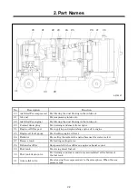
Page 15: ...ration 9 Pressure control valve For keeping the receiver tank pressure higher than 0 4MPa in the tank 10 Separator receiver tank For separating compressor oil from compressed air sent into the tank 11...

Page 16: ...ying and replenishing engine oil to engine 25 Engine oil level gauge For checking engine oil level 26 Radiator For cooling the coolant for engine because it is water cooled 27 Reserve tank For feeding...

Page 17: ...nnect the hook 1 of the crane or shackle with lifting bail 2 eye fitted at the top center of the unit and make sure that there is no person standing around the unit Then perform hoisting operation Use...

Page 18: ...hook 3 holder 2 and stopper 4 so carefully to prevent your fingers from being caught and injured 3 2 1 How to secure the drawbar Place the drawbar 1 to the front of the machine so that the wheel tire...

Page 19: ...hin 20 km h H000467 Be sure to use a vehicle with enough capacity to tow the unit in operating weight Standard pressure for a tire is at 0 45 MPa Be sure not to use wrong size or type of tire in chang...

Page 20: ...achine does not effect the other one Also a machine has to be installed in the environment where fresh air is always available Keep enough space around the unit for inspection and maintenance access 3...

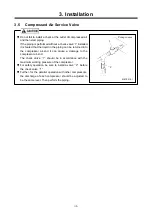
Page 21: ...he piping can be returned into the compressor air end it can cause a damage to the compressor air end The check valve 1 should be in accordance with the maximum working pressure of the compressor For...

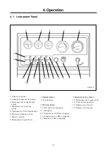
Page 22: ...ir filter clogging 1 Fuel level gauge 2 Coolant temperature gauge 3 Discharge air temperature gauge 4 Discharge air pressure gauge 5 Tachometer with hourmeter 6 Starting unloader valve 7 Starter switc...

Page 23: ...lter Lamp goes on when air filter gets clogged and suction resistance increases Actuating resistance is more than 6 23kPa Clean Replace The compressor stops when the emergency stop lamp goes on Be sur...

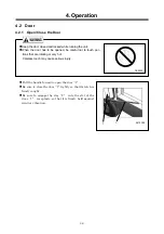
Page 24: ...l not to touch por tions that are rotating or very hot Careless touch may cause serious injury PK0028 Pull the handle foward to open the door 1 Be sure to close the door 1 tightly so that its latch is...

Page 25: ...ompressor Oil Be sure to use recommended oil listed below Recommended oil for compressor Temperature Brand Maker 5 to 40 MOBIL RARUS 425 MOBIL 15 to 40 MOBIL RARUS SHC 1025 MOBIL Even continuous oil r...

Page 26: ...ccording to the temperature Use LLC Antifreeze within the range of its mixing ratio between 30 and 60 If LLC Antifreeze in the water exceeds more than 60 it may decrease its antifreezing effect Upon d...

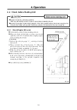
Page 27: ...peration wait 10 to 20 minutes after stopping engine before checking the oil level Procedure Pull out the oil level gauge 1 and wipe it with a clean cloth Then re insert the oil level gauge 1 fully an...

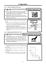
Page 28: ...ting out of the radiator could result in causing scalding Follow this procedure under all circumstances H990432 Do not continue operation at low coolant level Air bubble is mixed into radiator and it...

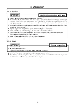
Page 29: ...mance Therefore never supply the oil higher than the proper oil level when the machine is on standstill 4 4 4 Drain Separator Receiver Tank After stopping the engine confirm that the pressure gauge in...

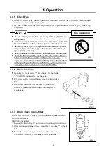
Page 30: ...hen fuel tank is filled up to the cap level fuel oil will be overfilled due to volume expansion caused by rise of ambient temperature Further fuel will be possibly spilled from fuel tank due to vibrat...

Page 31: ...adjust it Be careful not to leave any grease or LLC on a belt while changing it If any such material is left wipe it off completely 2 Check the water pump belt Procedure After loosening the nut fixing...

Page 32: ...t Check each wiring for any loose connection damage to insulating sheathed portion disconnection and short circuit 4 4 10 Check Piping of Each Part Check each piping for any loose connection and also...

Page 33: ...off Procedure Close fully service valves 1 Set the starting unloader valve 2 to START position Keeping pressing Stop button 3 turn the starter switch 4 to START position for cranking operation Repeat...

Page 34: ...d 4 5 3 How to Start the Unit at Low Temperature Use SAE10W 30 CD class for the engine oil Use LLC antifreeze Use correct amount to provide freeze protection according to the ambient tem perature Batt...

Page 35: ...immediately stop operation Then adjust the speed up to the standard one PDSE900S PDSF830S than 1 100min 1 PDSG750S than 1 200min 1 Be sure to check at times to see if gauges or each component of the u...

Page 36: ...is good when the discharge air blows off with a slight force in the following conditions H000476 2 1 Model Discharge air pressure gauge Tachometer Discharge air temperature gauge Coolant tem perature...

Page 37: ...the key and be careful not to lose it Unless all the service valves are fully closed upon stopping operation the compressed air will be sent in reverse direction in the hoses pipes connected to air t...

Page 38: ...ci fied interval But if such oil is found much more contaminated before the interval change the oil even before the specified pe riod comes In doing so replace the oil completely and use our recommend...

Page 39: ...ce abnormal noise or excessive heat should be checked d Loose bolt or nut should be checked e Any damage wear or shortage of machine components and parts should be checked f Performance of each part o...

Page 40: ...ing of auto relief valve Clean butterfly valve unloader Change diaphragm of vacuum relief valve Change o ring of vacuum relief valve Change o ring of pressure control valve Change rubber coupling Comp...

Page 41: ...ine feed pump 5 13 Check fuel hose 5 16 Clean inside of radiator Clean inside of fuel tank Change radiator hoses Engine Change wiring harness The items or parts marked show that they should be replace...

Page 42: ...roper level Too much oil could cause white smoke out of the exhaust and it can cause damage and accident to engine Procedure Loosen the drain valve 1 located outside of the frame to drain out the used...

Page 43: ...replacement parts refer to 5 5 5 6 3 Check Battery electrolyte Every 250 hours If there seems to be a problem in starting an engine due to a flat battery carry out the checks by following the procedur...

Page 44: ...place both internal shell 1 and 3 once in the proportion of replacing external ones four times The internal ones can never be reused even after they are cleaned When it is found that they cannot be re...

Page 45: ...se damage to bearings or serious accident like ignition in a separator receiver tank Be sure to change the oil completely at every scheduled interval Follow the designated regulations to dispose of co...

Page 46: ...ocedure Use a filter wrench to remove the cartridge 1 Spread thin film of oil on a packing 2 of a new cartridge 1 and screw it in For replacement parts refer to5 5 After a packing 2 touches the sealin...

Page 47: ...not holding it it could break the check valve So take care not to damage it 5 6 8 Change Air Filter Element Every 500 hours Air filter is an important part which is crucial to machine s performance an...

Page 48: ...imes using a filter wrench After installing a fuel filter be sure to check for oil leak during operation 5 6 10 Change filter of Pre filter Every 500 hours Procedure Take out the cover and element ins...

Page 49: ...leaned depending on the state of clogged tubes 1 even before maintenance schedule This unit is provided with the cover on both sides of the shroud to make it easy to clean both radia tor 1 and oil coo...

Page 50: ...iner 1 by loosening the joint bolt and clean it with diesel fuel oil and also using high air pressure blow At this time be sure to replace gasket For part numbers refer to 5 5 Then after finishing all...

Page 51: ...his eyes wash the eyes with clean running water and make him see a doctor immediately When LLC Antifreeze is stored put it in a container with an indication saying LLC Antifreeze inside and seal it u...

Page 52: ...n of compressor oil is unusually high and the differential pressure gauge of the oil separator reaches Red range change the oil separator Refer to 4 5 6 But note that the differential pressure gauge s...

Page 53: ...spection Maintenance 5 16 5 6 16 Check Fuel hose Every 2 000 hours or every 2 years When any crack or wear is found on the hoses change it even before the scheduled time Ask your nearest dealer for it...

Page 54: ...o sion as well as reduction of battery life Add distilled water so that the liquid level may reach the middle level between the UPPER and LOWER level without any delay Do not charge the frozen battery...

Page 55: ...t battery replacement be careful not to connect and terminals backwards Such a wrong connection will cause spark and damage each component Procedure for using a booster cable Stop the engine Connect o...

Page 56: ...lator rod 2 Faulty speed regulator 3 Fuel filter clogging 4 Engine trouble 5 Unloader orifice clogging Re adjust longer length Disassemble Check Disassemble Change Call your nearest dealer Disassemble...

Page 57: ...belt 5 Malfunction of by pass valve 6 Loose wiring connectors and disconnection 7 Faulty discharged air temp switch 8 Malfunction of oil check valve 9 Ambient temperature is lower than 15 or higher t...

Page 58: ...ng lubricant from the engine oil pan Pour new lubricant in the engine to clean its inside After running it for a while drain it again Spread lubricant on moving parts like speed regulator and rod end...

Page 59: ...acity L 105 Model MITSUBISHI FUSO TRUCK BUS CORPORATION 6D24 TE1 Type 4 cycle water cooled in line vertical direct injection turbo charged Number of cylinders bore stroke 6 130 mm 150 mm Total displac...

Page 60: ...8 Specifications 8 2 8 2 Outline drawing A040390 1 A070197...

Page 61: ...9 Wiring Diagram 9 1 A090360E...

Page 62: ...10 Piping Diagram 10 1 10 1 Compression air Compressor oil PDSE900S PDSF830S 4B1 A070141E 2...

Page 63: ...10 Piping Diagram 10 2 PDSG750S 4B1 A070220E 2...

Page 64: ...10 Piping Diagram 10 3 10 2 Fuel To engine Gauze filter Injection pump Fuel filter Fuel tank Pre filter Feed pump A070200...

Page 65: ...ECTION PART CHANGE HISTORY ETC RATED RPM rpm min 1 DISCHARGE AIR PRESS MPa OPERATION LOG OPERATION DATE OPERATION TIME AMBIENT TEMP ENG OIL REPLACEMENT HOUR h TOTAL OPERATION HOURS h COOLANT TEMP DISC...

Page 66: ...256 93 5571 FAX 0256 94 7567 8TH FLOOR SHINJUKU SAN EI BLDG 22 2 NISHI SHINJUKU 1 CHOME SHINJUKU KU TOKYO 160 0023 JAPAN TEL 81 3 3348 7281 FAX 81 3 3348 7289 URL http www airman co jp Copyright C 201...

Page 67: ......
Reviews: