5. Periodic Inspection/Maintenance
5
-
7
5.5.4 Check Insulation resistance
[Every 250 hours]
When the generator has not been operated for a long time or moisture has entered inside the
machine, be sure to measure the insulation resistance. If resistance is lower than 1M
Ω
, it could
cause an electrical leakage or fire. Dry the generator with compressed air until the resistance exceeds
1M
Ω
prior to operating.
Since the generator insulation may drop when moisture, oil vapor, and dust are stuck, always keep
the machine clean.
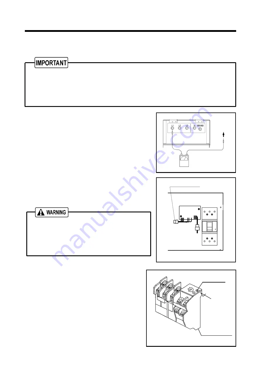
<Procedure> <Megger tester required>
①
Remove the load side cable from the output terminal
board.
②
Remove the cable between the terminal “N” and terminal
“Ground” which are connected on the back of the output
terminal plate.
③
Remove the AVR connector inside the generator control
panel.
④
Switch ON the three-phase breaker, measure each
insulation resistance between the terminals L1. L2. L3
terminal and bonnet.
⑤
Insulation resistance when measured with a 500 V
megger tester must be above 1 M
Ω
.
⑥
After finishing the measurement of insulation resistance,
re-connect the cable between the terminal "N" and
terminal "Ground".
After making sure that the insulation resistance of the
generator is higher than 1 M
Ω
, be sure to re-connect the
cable between the terminal "N" and terminal "Ground" just
as it was originally connected.
If it is left disconnected, the grounding becomes imperfect
so that it could cause electric shock
.
5.5.5 How to check thermal relay
[Every 250 hours]
<Procedure>
①
Turn the starter switch to ON.
②
Set the main breaker to ON.
③
The three phase main breaker will trip if you push
the test lever of the thermal relay in the arrow
direction.
④
Note that once the three phase main breaker trips
to the off position, the single phase breaker that
supplies power to the GFCI outlets can still be ON.
A040180-1
Bonnet
A060468
Thermal relay
Test lever
Push
AVR Connector
A080518
Discount-Equipment.com
Summary of Contents for SDG40S-8B1
Page 1: ... www discount equipment com D i s c o u n t E q u i p m e n t c o m ...
Page 63: ...8 Specifications 8 4 Unit mm A100398 D i s c o u n t E q u i p m e n t c o m ...
Page 66: ...D i s c o u n t E q u i p m e n t c o m ...
Page 67: ...10 Piping Diagram 10 1 10 1 Fuel piping A100427E D i s c o u n t E q u i p m e n t c o m ...


