background image

5

ELECTRICAL CONNECTIONS

Connect the mains lead to a standard, 230 Volt (50Hz) electrical supply 
through an approved 13 amp BS 1363 plug, or a suitably fused isolator switch.

If the plug has to be changed because it is not suitable for your socket, or 
because of damage, it must be removed and a replacement fitted, following 
the wiring instructions shown below. The old plug must be discarded safely, as 
insertion into a power socket could cause an electrical hazard.

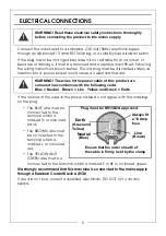
If the colours of the wires in the power cable do not agree with the markings 
on the plug.

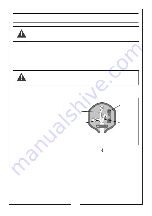
• The BLUE wire must be 

connected to the 
terminal which is 
marked N or coloured 
back.

• The BROWN wire must 

be connected to the 
terminal which is 
marked L or coloured 
red.

• The YELLOW AND 

GREEN wire must be 
connected to the terminal which is marked E or

 or coloured green.

We strongly recommend that this machine is connected to the mains supply 
through a Residual Current Device (RCD)

If you are not sure, consult a qualified electrician. DO NOT try to do any 
repairs. 

WARNING! Read these electrical safety instructions thoroughly 
before connecting the product to the mains supply.


WARNING! The wires in the power cable of this product are 
coloured in accordance with the following code:


Blue = Neutral   Brown = Live   Yellow and Green = Earth

Plug must be BS1363/A approved.

Always fit 

Ensure that the outer sheath of 

Neutral

(Blue)

Live

(Brown)

Earth

(Green and 

a 13 Amp 

the cable is firmly held by the clamp

fuse.

Yellow)

Summary of Contents for 2244025

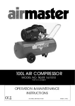
Page 1: ...OPERATION MAINTENANCE INSTRUCTIONS LS0620 ISS 6 ORIGINAL INSTRUCTIONS 100L AIR COMPRESSOR MODEL NO TIGER 16 1010 PART NO 2244025...

Page 2: ...which it was intended Faulty goods should be returned to their place of purchase no product can be returned to us without prior permission This guarantee does not effect your statutory rights ENVIRON...

Page 3: ...ying flammable materials e g cellulose paint ensure that there is sufficient airflow and keep clear of any source of ignition 11 Before spraying any material always consult paint manufacturers instruc...

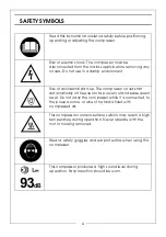
Page 4: ...pressor could start automatically in the event of a power cut and subsequent reset Do not carry the compressor while it is connected to the power source or when the tank is filled with compressed air...

Page 5: ...oured back The BROWN wire must be connected to the terminal which is marked L or coloured red The YELLOW AND GREEN wire must be connected to the terminal which is marked E or or coloured green We stro...

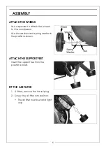
Page 6: ...compressor Use the washers and spring washer in the positions shown ATTACH THE SUPPORT FEET Insert the support feet into the position shown FIT THE AIR FILTER 1 If fitted remove the travel plug 2 Scr...

Page 7: ...ER CAP 1 Remove the travel plug 2 Insert the oil filler cap MOVING THE AIR COMPRESSOR Stop the compressor and disconnect it from the power supply before you move it Always use the handle To prevent da...

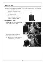
Page 8: ...d down Make sure that the compressor is on level ground Make sure that the supply voltage matches the voltage shown on the data label CHECK THE OIL LEVEL 1 Make sure that the oil level is half way up...

Page 9: ...on position NOTE The outlet valve is shown without the air hose fitted for clarity TURNING THE COMPRESSOR ON 1 Plug the compressor into the power supply 2 Lift the On Off button The compressor will op...

Page 10: ...and outlet valve Turn clockwise to increase the pressure Turn counterclockwise to decrease the pressure GAUGES 1 The reservoir pressure gauge shows the current pressure in the reservoir 2 The outlet p...

Page 11: ...reservoir You will hear a hissing sound as the reservoir depressurises Do not leave the compressor unattended if the reservoir is pressurised DRAINING THE RESERVOIR 1 Turn the compressor off and disc...

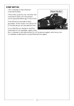
Page 12: ...er which prevents damage to the motor If the thermal overload device operates let the motor cool down for 5 minutes and push the reset button If you start the compressor and the overload cutout operat...

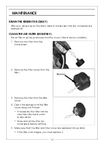
Page 13: ...1 Remove the filter from the compressor 2 Remove the filter cover from the filter 3 Remove the filter from the filter cover 4 Clean the sponge and the filter cover using a soft brush If necessary the...

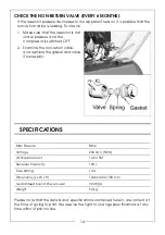
Page 14: ...he non return valve and replace the gasket and valve if necessary SPECIFICATIONS Max Pressure 8 Bar Voltage 230 VAC 50Hz Air Displacement 14 5 CFM Receiver Capacity 100 L Fuse Rating 13 A Dimensions L...

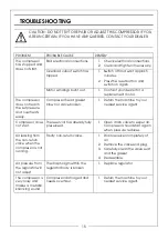
Page 15: ...ats easily Compressor head gasket blown or valve broken 1 Return the machine to your nearest service agent Compressor does not start The reservoir has already fully pressurised 1 Open drain valve to e...

Page 16: ...16 EXPLODED DIAGRAM...

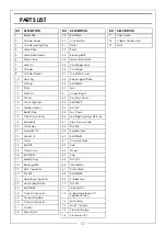
Page 17: ...tor 35 Connecting Pipe 36 Curved Connector 37 Air Filter 38 Reset Switch 39 Bolt M4x6 40 Junction Box 41 Stator 42 Rotor 43 Brearing 6202 44 Wave Washer D35 45 Centrifugal Floor 46 Centrifuge 47 The M...

Page 18: ...18 DECLARATION OF CONFORMITY...

Page 19: ...19 DECLARATION OF CONFORMITY...

Page 20: ......

Reviews: