13
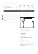
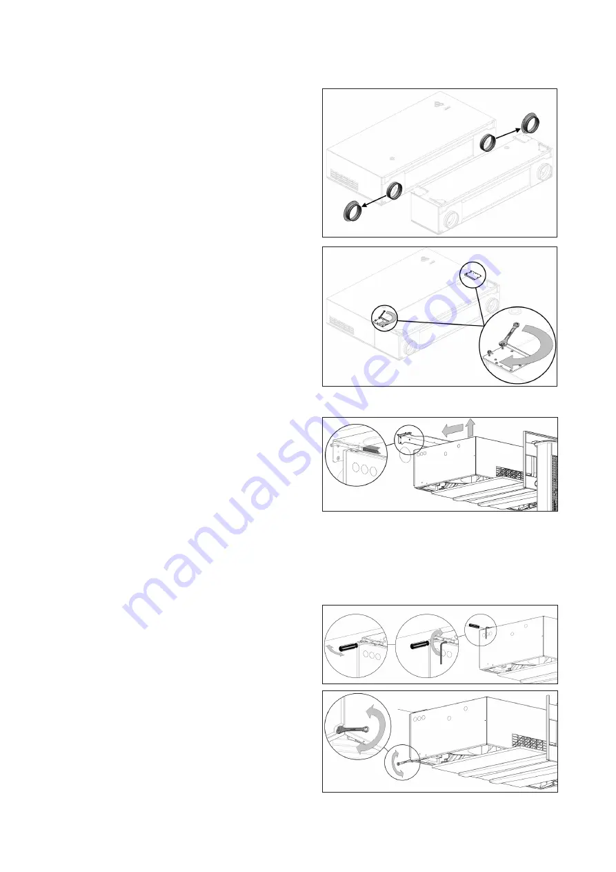
3.6.2. Installation of the Air Handling Unit
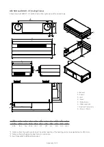
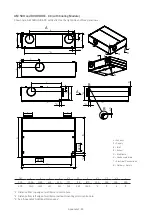
The unit has to be adjust into a horizontal position.
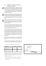
1. Lift the air handling unit up to the frame, using
appropriate lifting equipment.
When lifting the unit a protective underlay must be placed
beneath the unit to prevent scratches to the unit. This
underlay may for example be strong, clean cardboard or
equivalent.
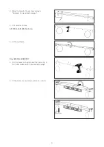
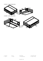
2. Draw the leads and the condensate hose of the unit
from the connection points past the frame.
3. Push the unit onto the frame.
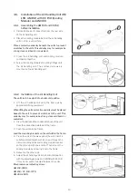
Lead the mounting brackets on the unit within the frame.
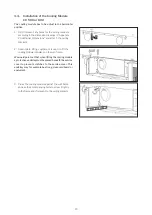
4. Press the unit all the way against the wall; insert a
suitably pointed object, such as an awl, through the
frame’s centring holes and cooling module bracket
so they line up with one another. Then mount the
cooling module by screwing it onto the frame.
5. Repeat on the other side.
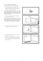
6. Adjust the air handling unit into a horizontal position
with the adjusting screws. For AM 150 with CC 150,
it may be necessary to adjust between the units.
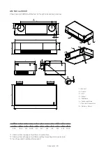
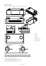
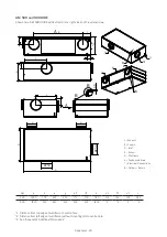
Max pressure per adjusting screw:
AM 150: 330 N
AM 150 + CC 150: 737 N
AM 300: 450 N
1.
2.
3.6. Installation of the Air Handling Unit AM
150, AM 150 with CC 150 (Cooling
Module) and AM 300
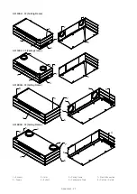
3.6.1. Assembling the AM 150 and CC 150
before installation
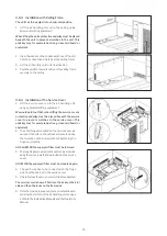
1. Dismantle any duct connectors from the rear side
of the air handling unit.
2. Place the cooling module behind the air handling
unit on a firm, even surface.
Place a protective underlay beneath the units to prevent
scratches to the units. This underlay may for example be
strong, clean cardboard or equivalent.
3. Press the air handling unit and cooling module
completely together.
4.
Screw the cooling module’s mounting fittings onto
the air handling unit. The enclosed screws are
mounted on the air handling unit.


