a
g
g
e
d
c
b
f
k
i
*4
*4
h
*4
*4
*4
*4
*4
*4
*4
*4
*4
*4
1
2
6
7
4
8
3
A
A
5
-0
+20
-0
+20
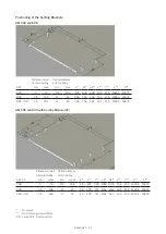
a
b
c
d
e*1
f
g
h*1
i*2
k
1600
779
1570
1621
437
764
250
170
202
1170
1910
916
1880
1931
472
901
315
250
266
1433
Appendix 1 - 21
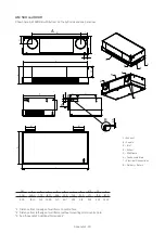
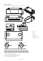
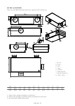
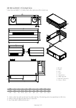
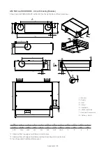
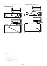
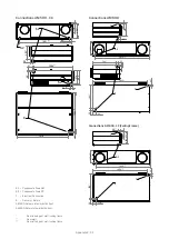
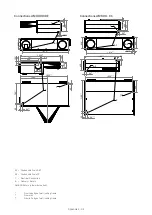
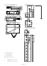
AM 500 and 800 H - CF (Ceiling Frame)
Shown here: AM 500 HT - CF with Extract on the right side and three panel rows.
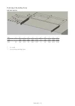
*1 Distance from the wall to centre hole. The vertical position of the handling unit can be adjusted up to +20/-0 mm.
*2 Distance from left edge of ceiling frame to centre hole.
*4 See ”Appendix 2 Additional Dimensions”.
AM
500
800
1 = Exhaust
2 = Supply
3 = Inlet
4 = Extract
5 = Ceiling Frame
6 = Condensate drain
7 = Electrical Connections
8 = De Return


