WARNING
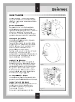
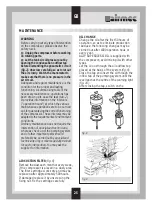
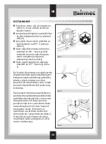
For three-phase motors the working
direction is to be controlled. The
direction is indicated by a red arrow
attached to the belt cover.
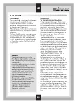
CONNECTION
TO THE PNEUMATIC SYSTEM
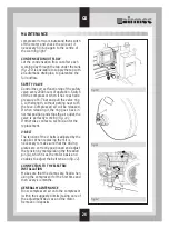
The connection of the compressor to the
system of compressed air distribution
must
be carried out with the use of a flexible pipe,
minimum 60 cm long, and with an adequate
width to be properly connected to the
compressor.
For the correct functioning of the
compressor, it is necessary to connect the
compressor to a
closed or ring circuit
distribution system. This reduces load losses
to the minimum and allows for the
homogeneous distribution of compressed
air in the system.
The pipes are to be of appropriate size, free
of weldings (Mannesmann type) and made
of a plastic material adequate for working
with compressed air. If metal pipes are used,
make sure they have an inner galvanic
protection.
WARNING
Use flexible pipes 1 1/2 times as wide
as the air outlet taps, since
consequent load losses might lead to
a reducttion in the power of the
compressor, and thus an increased
minimum working pressure might
compromise the global output of the
compressor.
Avoid narrowings of any kind in the
circuit; it is advisable to use elbow
joints with a long radius of curvature.
Provide the tank outlets and the
network with sluice valves for the
tapping of compressed air, which
allow for interventions along the line.
A connection to an emergency system
in case of malfunction of the main
compressor should be also provided.
The valves and the joints must have
a size adequate for the air outlet.
Position the air circuit with a 1%
gradient in order to allow
condensation settling on the bottom
of the tanks in the lowest parts of the
network to flow out.
Use automatic drainpipes or
discharging taps for standard models
for eliminating the condensation.
INSTALLATION
GB
21
Summary of Contents for HOBBY Series
Page 2: ......
Page 6: ...INSTALLAZIONE 6 I...
Page 20: ...INSTALLATION GB 20...
Page 64: ...007301996 D O C...

