10
UVHEALTH BIO2000 Installation Manual
3. Install the UVHealth BIO2000 unit:
Never expose eyes or skin to UV-C light from any
source. Looking directly at the UV-C light may
cause permanent eye damage or blindness. Never
operate the UVHealth BIO2000 Air Purifying
System out of the plenum. Avoid touching the
glass portion of the lamp with your hands.
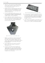
a. Remove two Phillips head screws on the left and
right hand side of the front electrical cover and
remove the cover
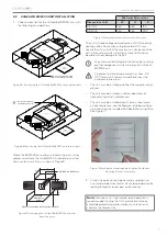
b. Hold or temporarily tape the included Ductboard
Mounting Plate in the location chosen for
installation, and using the plate as a template, mark
the mounting surface using the outermost slots in
the plate (see Figure 11). Alternatively, a 136.5 mm
square may be marked on the mounting surface.
c. Cut out the opening for the unit in the mounting
surface, making sure to cut slightly outside the
marked lines if the Ductboard Mounting Plate was
used as a template.
d. If mounting the unit on ductboard, attach the
Ductboard Mounting Plate to the opening by
folding the inner flaps of the plate into the opening
and fully back against the inside of the opening in
the ductboard, either from the sides or from top
and bottom of the plate. Finish the Ductboard
Mounting Plate installation by sealing around the
edges of the plate to the ductboard, using mastic
foil tape or other material suitable for sealing duct
joints.
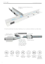
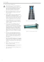
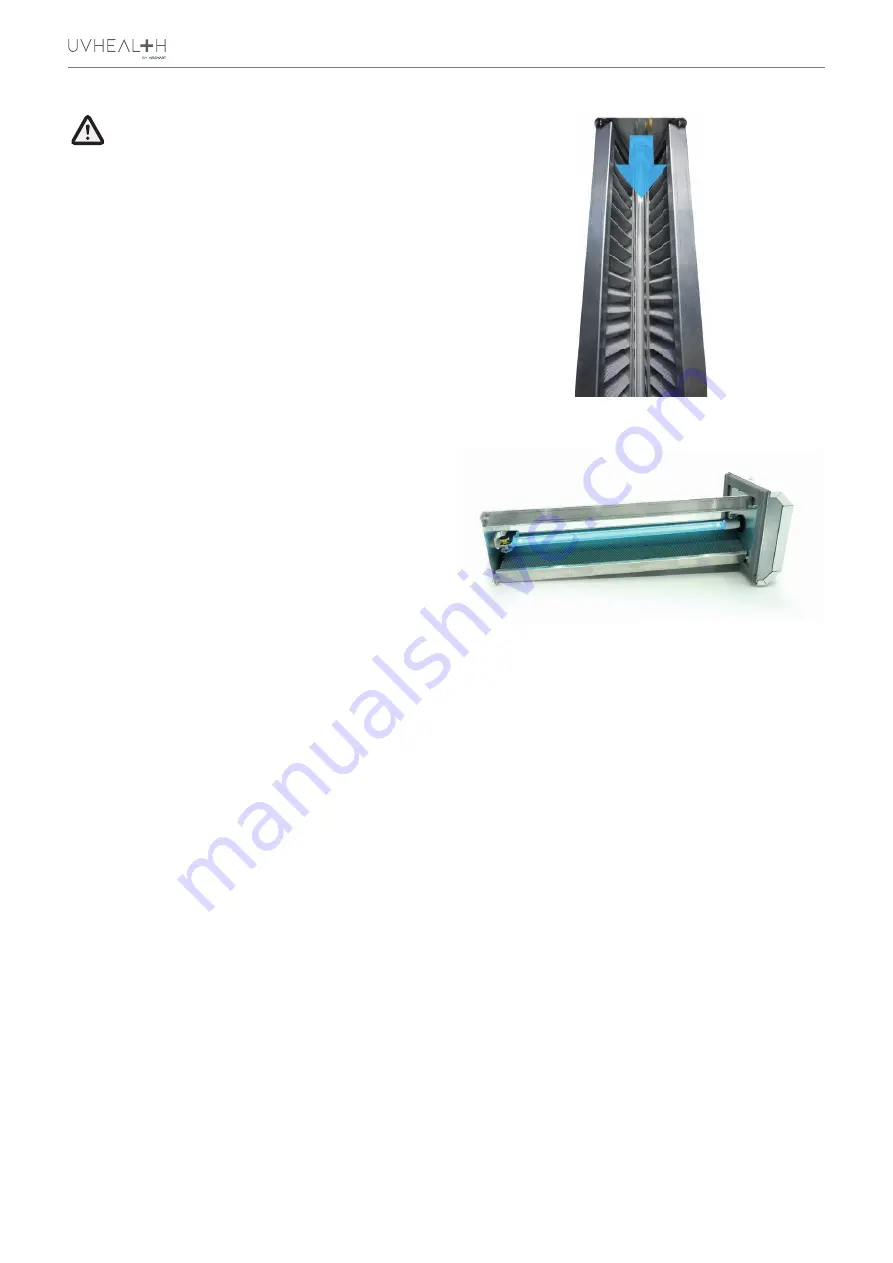
e. Insert the unit into the duct opening and attach
it to the duct (or Ductboard Mounting Plate) with
the four included sheet metal screws. The wider
side of the V-shape of the UVHealth BIO2000 unit
panels should face into the oncoming airstream,
see Figure 12.
f.
The UVHealth BIO2000 models are configured for
upward or horizontal air flow direction as shipped. If
the direction of airflow in the duct is downward, the
whole unit may be rotated, so that airflow matches
Figure 12.
g. Reattach cover using two sheet metal screws
previously removed in step 3a.
h. Attach the quick connect power cord and plug in to
any standard electrical outlet.
i.
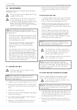
Verify lamp operation by looking through the view
port on front cover.
Figure 12: Unit showing direction of airflow
Figure 13: Unit showing lamp in operation

