Interior
5-20
2019 Tommy Bahama TC
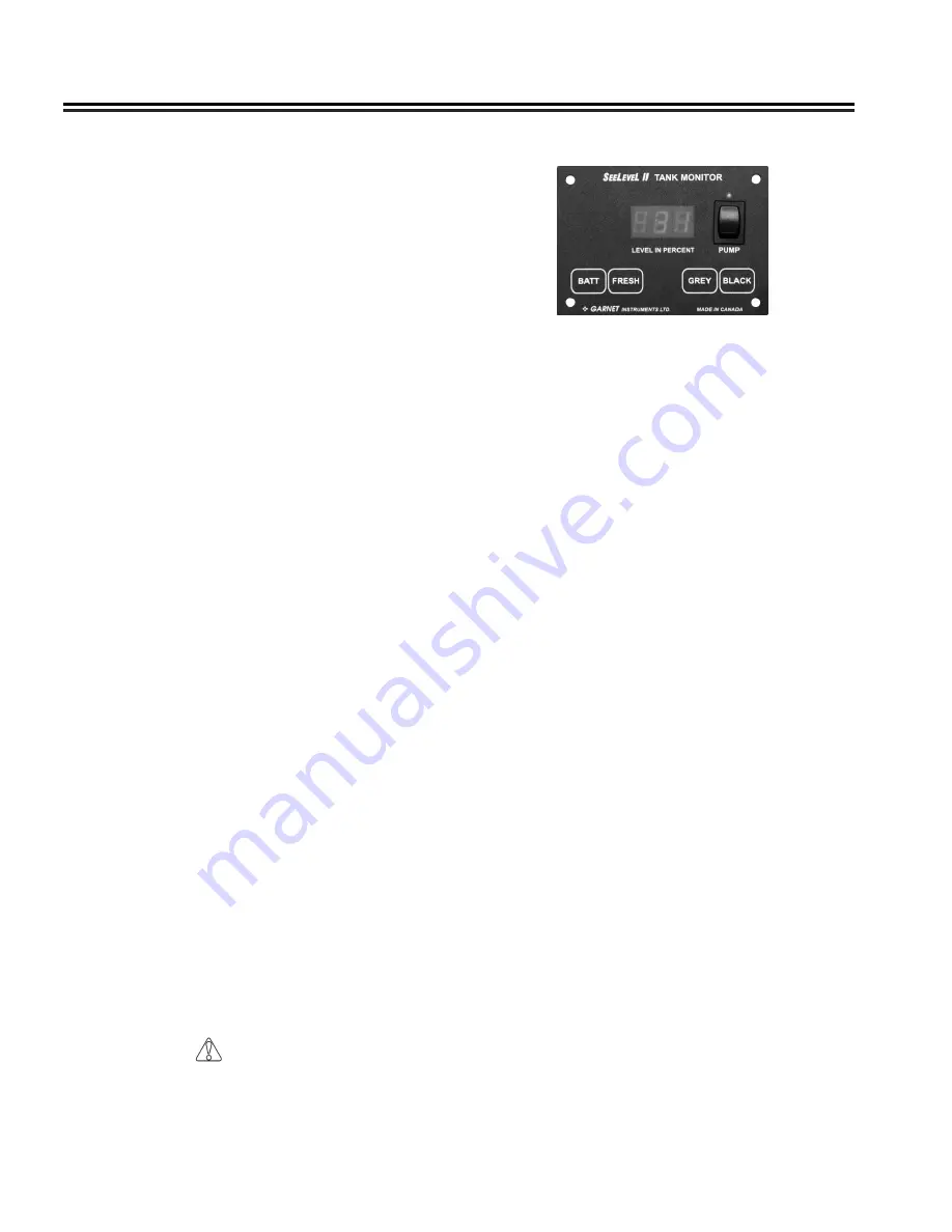
SeeLevel II Monitor Panel
The display is the only system component that is
accessed by the user� The display shown above is
located in the overhead cabinet behind the drivers
seat� All user input to the display is done using the four
buttons along the bottom of the display�
NOTE
The following information is for use of the SeeLevel
II Monitor Panel. The Multiplex Systems main
control panel can also be used.
The display receives the information from the three
sender pads via a single, two-conductor wire, and
displays the level information in percent of full on a
three-digit, LED display� When the front panel button
for a particular tank is pressed, the display powers
up and displays the level for that tank� If the button
is pressed and released, the display will show the
level for about 5 seconds and then shuts down
automatically� If another button is pressed before the
display shuts down, then the new level will immediately
be shown� If the same button is pressed twice, the
display will hold on that tank and continue to show
updated levels for 5 minutes before shutting off� This
allows the user to monitor the filling or draining of the
tank� By pressing two buttons at once, the diagnostic
functions can be accessed�
Sender pads are installed and stuck to the sides of
the holding tank� The sender pad scans the water
level through the tank wall using digital techniques
programmed into the sender microprocessor�
Refrigerator/Freezer
Review all refrigerator literature supplied in your
owner’s packet or stored in the refrigerator prior to
operating it�
Operation
The refrigerator operates on 12-volt current from
the battery� All units are supplied with a wide range
thermostat designed to sense the evaporator (cold
plate) temperature� The coldest position on the
thermostat is reached by turning the knob to the
right (clockwise); conversely turning the thermostat
knob to the left (counterclockwise) yields a warmer
setting� The OFF position is reached by turning hard
counterclockwise past the click� The reference point is
shown with an indicator sticker beside the knob�
Start up
Turn the power on and set the thermostat between 3
and 4� You can make further adjustments to suit your
personal requirements after the box has cooled down�
Allow the refrigerator to come down to temperature
before loading with product� Adding pre-cooled product
will help keep the temperature stable when loading�
Setting the thermostat to a higher setting e�g�, 7, will
not decrease the time required for the unit to cool down
to its normal operating temperature�
NOTE
The refrigerator requires 12V power to operate.
You must have the battery disconnect switch in the
use position even if plugged into shore power.
Defrost and Cleaning
The frequency of defrost is dependant on the number
of door openings, the ambient temperature and the
humidity level� Typically, it is a good practice to defrost
once there is ¼ inch of frost buildup on either side of
the evaporator (cold plate)� When defrosting, the unit is
shut off by turning the thermostat counterclockwise to
the OFF (0) position� Prop the door open� We suggest
placing a towel in the bottom of the refrigerator to catch
excess moisture�
Now that the unit has been defrosted, the interior can
be cleaned with a non-abrasive cleaner� Do not use
“Brillo” or “SOS” type abrasive pads, as they will score
the surfaces� Baking soda is recommended�
CAUTION
Speeding up the defrost process with a knife
or scraper is strongly discouraged due to the
likelihood of rupturing the refrigerant circuit.
Summary of Contents for TOMMY BAHAMA 2019
Page 1: ...2019 TOMMY BAHAMA OWNER S MANUAL ...
Page 4: ...2019 Tommy Bahama TC NOTES ...
Page 6: ...2019 Tommy Bahama TC 1 2 Introduction NOTES ...
Page 16: ...2019 Tommy Bahama TC 2 10 Safety NOTES ...
Page 28: ...2019 Tommy Bahama TC 3 12 General Information NOTES ...
Page 104: ...Maintenance 9 18 2019 Tommy Bahama TC 12 Volt Schematic ...
Page 105: ...Maintenance 2019 Tommy Bahama TC 9 19 12 Volt Schematic ...
Page 106: ...Maintenance 9 20 2019 Tommy Bahama TC 12 Volt Schematic ...
Page 107: ...Maintenance 2019 Tommy Bahama TC 9 21 12 Volt Schematic ...
Page 108: ...Maintenance 9 22 2019 Tommy Bahama TC 12 Volt Schematic ...
Page 109: ...Maintenance 2019 Tommy Bahama TC 9 23 12 Volt Schematic ...
Page 110: ...Maintenance 9 24 2019 Tommy Bahama TC 12 Volt Standard Parts List ...
Page 112: ...Maintenance 9 26 2019 Tommy Bahama TC 30 Amp 120 Volt Standard Parts list ...
Page 116: ...Maintenance 9 30 2019 Tommy Bahama TC Multiplex Circuit Control Board Layout ...
Page 117: ...Maintenance 2019 Tommy Bahama TC 9 31 Multiplex Networking Diagram and Switch Panel Layout ...
Page 121: ...Maintenance 2019 Tommy Bahama TC 9 35 NOTES ...
Page 122: ...2019 Tommy Bahama TC 9 36 Maintenance NOTES ...
Page 125: ......


