5
We recommend the following procedure to familiarize
yourself with the components of your system and as
preparation for installation in your model.
1.
Remove the transmitter from the package box.
2.
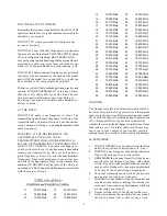
Affix frequency channel identifier plaques to
the transmitter a s shown in picture below.
3.
Charge the receiver and transmitter batteries
as stated in the Installation and Guidelines
Manual. DO NOT QUICK CHARGE
BATTERIES AT ANY TIME.
4.
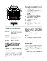
Switch on the transmitter and note the LED
display meter indicating the unit is operatin g.
The LED display will light up and indicate the
state of charge of the internal NiCd battery
pack. Plug in the AC charger in the wall outlet
and connect the proper leads in the transmitter
and receiver battery and let charge for a full
24 hours for the first initial charge. After both
batteries are fully charged, note the LED
display to make sure that the FULL light is
operating properly. If the FULL LED will not
light up after a 24-hour charge, your
transmitter RF output maybe weak, this will
need to be sent to AIRTRONICS to be
checked.
5.
Switch “off” the transmitter and remove all of
the other components from the foam packing
box containing your AIRTRONICS
VG400/VG600 FM radio control system.
6.
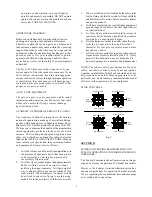
Figure 2 shows how to connect the
components of your system together. Note the
servo and switch harness plugs are inserted in
the receiver. This will allow you to switch the
receiver battery on and or off. At this point,
your objective is to get the system operating
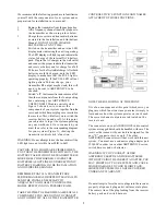
on your workbench. Once connected, you
must then refe r to the corresponding diagram
for your system (Figure 3), showing the
transmitter control stick’s function.
WARNING: Do not attempt to use the transmitter if the
LED lights are not visible from MID to Full.
CAUTION: IF NO LIGHTS ARE VISIBLE WHEN
YOU TURN THE TRNSMITTER SWITCH ON, THE
BATTERY PACK WITHIN THE TRANSMITTER IS
MORE LIKELY DISCHARGED. CHARGE THE
BATTERIES AS OUTLINED UNDER SECTION IV
BATTERY CHARGING, IN THE INSTALLATION
AND GUIDELINES MANUAL.
REMEMBER THAT IF A TRANSMITTERS
PERFORMANCE HAS DROPPED IT MAY FAIL TO
SEND THE SIGNALS NECESSARY TO
ADQUATELY AND SAFELY CONTROL THE
MODEL RESULTING IN A POSSIBE CRASH.
TAKE THE TIME TO LEARN THE NAMES OF ALL
COMPONENTS YOU ARE GOING TO CONNECT
AND TO IDENTIFY ALL OF THE TRANSMITTER
CONTROL STICK’S FUNCTIONS AND NAMES
ATTACHED TO THOSE FUNCTIONS.
NOTE THE FOLLOWING AT THIS POINT:
It is of no consequence at this point which servo you
plug into which function since your aim is simply to
learn and see how the system operates on your bench.
The correct channel outputs are indicated on the
receiver case.
The connectors on your AIRTRONICS radio control
system are rugged but should be handled with care. The
receiver that came with your unit is designed for the
new “Z” connector servos only. The older
AIRTRONICS connectors will not work with this new
system. You must use a connector plug adapter part
#99400Z in order to use older AIRTRONICS servos,
switch harness and or batteries.
WARNING: IF YOU CONNECT OLDER
AIRTRONICS SERVOS AND OR BATTERIES
WIT HOUT USING THE CORRECT ADAPTER, YOU
MAY SHORT OUT YOUR SYSTEM AND CAUSE
MAJOR DAMAGE TO YOUR FLIGHT PACK.
SHORTED SYSTEMS WILL NOT BE COVERED
UNDER ANY WARRANTY.
Do not attempt to force the servo plugs into the receiver;
properly align each plug and it will move into place.
The same is true of the plug leading from the receiver
battery pack and switch harness.

