31
7 - START-UP
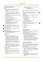
START-UP SEQUENCE
√
Start-up sequence
1
Powered unit
2
Unit ON
3
Check for unusual vibrations or noise with the compressor and fans activated
4
Verify that the inlets/outlets in the room and any dampers in the conduits are open
5
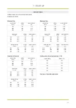
Check the airflow (anemometer) by taking a reading directly on the external inlets and outlets (see table on
page 33)
6
If impossible to access the external inlets/outlets than check the airflows in the room using the following
formula:
Airflow m
3
/h = Area (m
2
) x Speed (m/s) x 3600 seconds
7
Fans operation check
8
With the compressor on, verify that the unit's power supply voltage falls between 207-253 V
9
No anomalous vibrations check
10
Instruct the customer on how to switch the device on/off, change the set-point and clean the filter
11
Collect all the machine documentation and give it to the customer together with the commissioning report duly
completed and signed.
During the initial start-up procedure, the airflow is setting (from HMI) to check the balance amount of air entering and exiting the
environment.
Door and windows must be mounted.
External doors and windows must be closed.
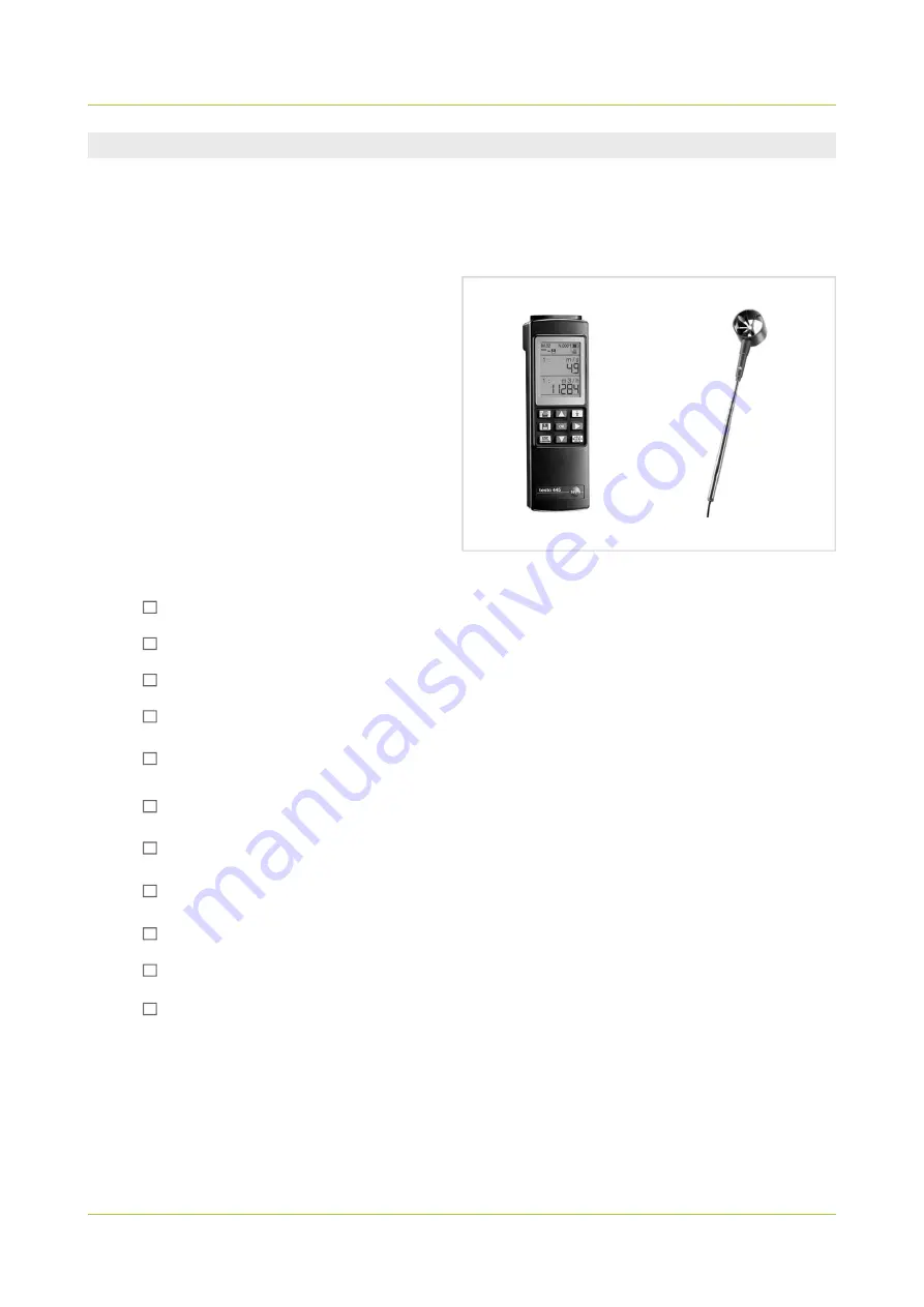
Instruments needed in addition to normal instruments.
•
Anemometer complete with probe to measure the differential
pressure and vane probe.
•
Aeraulic system plan compete with flow rates into the
individual rooms.
•
Rectangular and circular extensions to rest on the inlets in
rooms in order to ensure an even air flow rate of the supply
nozzles and extraction valves when this is measured.
Summary of Contents for AIRFLOW2020
Page 2: ......
Page 11: ...9 NOTES...
Page 35: ...33 NOTES...
Page 69: ...67 NOTES...
Page 70: ...68 NOTES...
Page 79: ...9 NOTES...
Page 103: ...33 NOTE...
Page 138: ...68 NOTE...
Page 139: ...74 NOTE...

