28
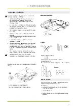
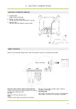
Main control board
6 - ELECTRIC CONNECTIONS
ELECTRICAL CONNECTION DIAGRAM
REMOTE CONTROLS
A - Keyboard HMI
Cable
5x0,75
mm
2
shielded
B - 220/240 ~50HZ power supply
Provide the power outlet ( on/off schuko)
C - Electrical panel
Auxliary
connection
(Modbus, remote On/Off)
Refer to the unit electrical diagram (the number of the diagram is shown on the serial number label).
B
A
C
Remote summer-winter selector switch (heat/cool)
It allows the change of the operating mode from heating to
cooling from an external control.
On - Off
Switch on / off from a remote control
Silent
It reduces the fan speed, and limit s the compressor
frequency. It is possible to setting 2 types of silence:
normal silent, ultra silent
Ventilation (fan)
Only the fans are actives and no check on the temperature
and humidity is performed the compressor is disabled
Summary of Contents for AIRFLOW2020
Page 2: ......
Page 11: ...9 NOTES...
Page 35: ...33 NOTES...
Page 69: ...67 NOTES...
Page 70: ...68 NOTES...
Page 79: ...9 NOTES...
Page 103: ...33 NOTE...
Page 138: ...68 NOTE...
Page 139: ...74 NOTE...

