CONTROL SYSTEM
11-27
SM TELECOM 1-A.0 GB
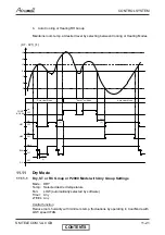
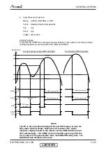
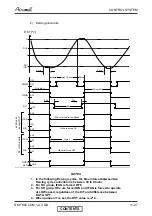
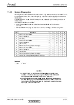
2) Deicing procedure
OCT [
o
c]
ON
OFF
ON
OFF
ON
L
ANY
COMP
OFAN
RV
IFAN
DST
(DDT)
0
12
OFF
HEs are forced ON
DOC
ANY
ON
HE
36s
36s
DT
30s
max 12 min.
Note 3
DI (note 1)
DI (note 2)
30s
3 min
3 min
IFAN
OFF
ANY
HE
OFF
ANY
al
l SH units
exc
e
pt WAX
RC
or WAX units
HEs are forced OFF
IFAN is forced to Low Speed
BLINK
ON
OPER
LED
NOTES
1. In the following Deicing cycles, the time interval between two
Deicing cycles activation is between 30 to 80 min.
2. For RC group, IFAN is forced OFF.
3. For SH group, HEs are forced ON and IFAN is forced to operate
at LOW speed, regardless of the ICT and difference between
RAT & SPT.
4. When jumper J7 is set, the DST value is -2°C.
CONTENTS
Summary of Contents for GC 12 LT
Page 13: ...OUTLINE DIMENSIONS 4 3 SM TELECOM 1 A 0 GB 4 5 Outdoor Unit GC 30T LT CONTENTS...
Page 28: ...CONTROL SYSTEM 11 3 SM TELECOM 1 A 0 GB 11 1 4 Main PCB Controller CONTENTS...
Page 70: ...EXPLODED VIEWS SPARE PARTS LISTS 13 6 SM TELECOM 1 A 0 GB 13 6 Outdoor Unit GC 12 LT CONTENTS...
Page 72: ...EXPLODED VIEWS SPARE PARTS LISTS 13 8 SM TELECOM 1 A 0 GB 13 8 Outdoor Unit GC 18 LT CONTENTS...
Page 87: ...APPENDIX A 15 1 SM TELECOM 1 A 0 GB APPENDIX A INSTALLATION AND OPERATION MANUAL CONTENTS...

