OPTIONAL ACCESSORIES
14-5
SM TELECOM 1-A.0 GB
2
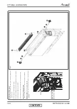
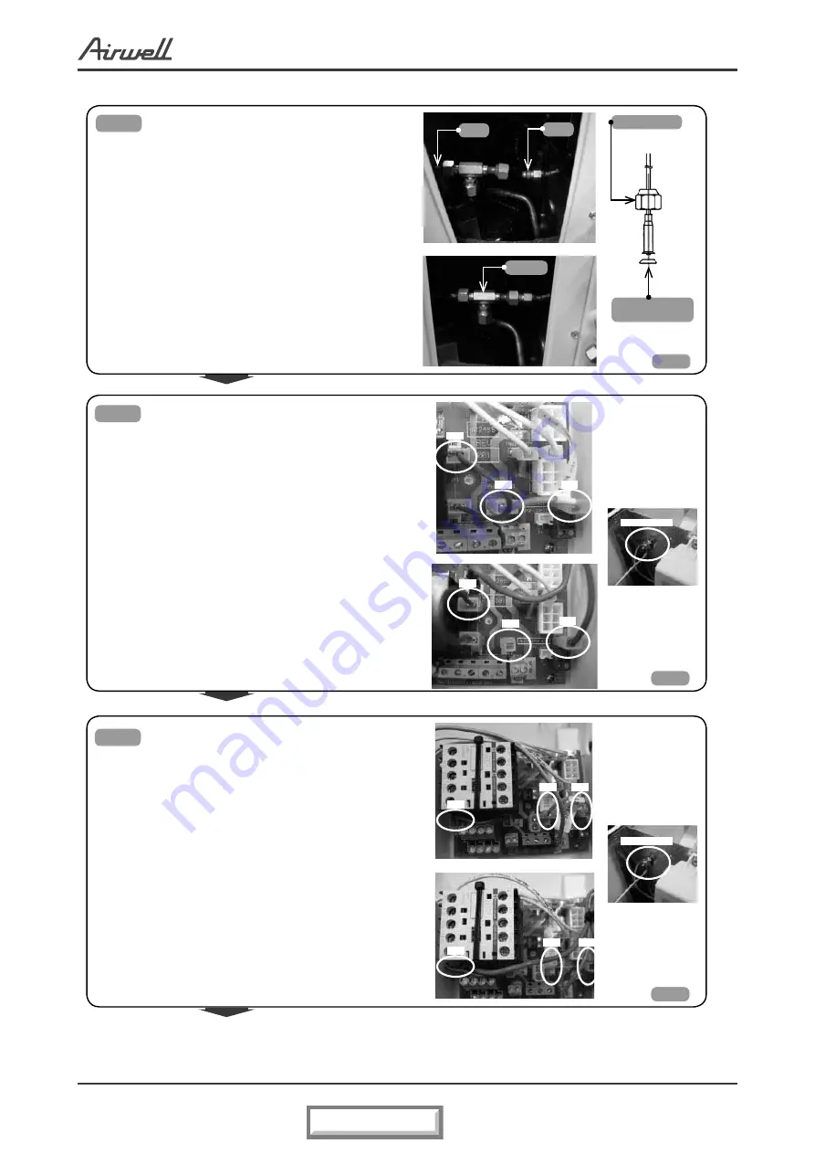
Fig.4
●
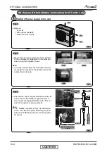
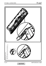
Connect capillary
E
to
T-valve
.
Use Copper sealing gasket between the flare nut
and the connection to
T-valve.
Note:
● Installing the Copper sealing gasket is mandatory
in order to avoid refrigerant leak.
Cooper sealing
gasket
Fig.5
Fig.6
E
T-valve
D
Flare nut
TB2
TB5
TB4
TB1
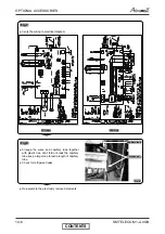
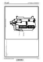
Electrical connections for 3PH units:
●
Disconnect the wire from point “6”
on main ter-
minal PCB Typhoon and isolate it with isolation
tape.
●
Disconnect the JP1 and JP2 wires from tabs
TB1;
TB8; TB9 on PCB Typhoon.
●
Connect Red Wire from Fan Speed
Controller to
tab “TB8” on PCB Typhoon.
●
Connect Green Wire from Fan Speed
Controller
to Tab “TB1” on PCB Typhoon.
●
Connect Y/Green wire from Fan
Speed Controller
to ground screw on units partition.
●
Return “JP1” wire, previously disconnected,
to
Electrical connections for 1PH units:
●
Disconnect the wire from point “6” on main ter-
minal outdoor PCB Typhoon and isolate it with
isolation tape.
●
Disconnect the JP1 and JP2 wires from tabs TB2;
TB4; TB5 on PCB Typhoon.
Connect the Red Wire from Fan Speed Controller
to tab “TB4” on PCB Typhoon.
●
Connect Green Wire from Fan Speed
Controller
to tab “TB2” on PCB Typhoon.
●
Connect Y/Green wire from Fan Speed Controller
to ground screw on units partition.
●
Return “JP1” wire, previously disconnected, to
tab “TB2”.
Ground screw
TB2
TB5
TB4
Ground screw
Fig.5
Fig.4
Fig.6
TB8
TB9
TB1
TB8
TB9
CONTENTS
Summary of Contents for GC 12 LT
Page 13: ...OUTLINE DIMENSIONS 4 3 SM TELECOM 1 A 0 GB 4 5 Outdoor Unit GC 30T LT CONTENTS...
Page 28: ...CONTROL SYSTEM 11 3 SM TELECOM 1 A 0 GB 11 1 4 Main PCB Controller CONTENTS...
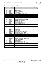
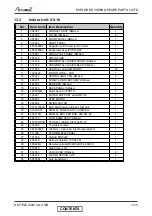
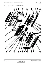
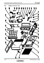
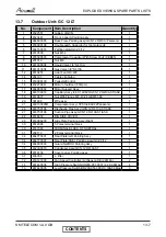
Page 70: ...EXPLODED VIEWS SPARE PARTS LISTS 13 6 SM TELECOM 1 A 0 GB 13 6 Outdoor Unit GC 12 LT CONTENTS...
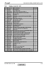
Page 72: ...EXPLODED VIEWS SPARE PARTS LISTS 13 8 SM TELECOM 1 A 0 GB 13 8 Outdoor Unit GC 18 LT CONTENTS...
Page 87: ...APPENDIX A 15 1 SM TELECOM 1 A 0 GB APPENDIX A INSTALLATION AND OPERATION MANUAL CONTENTS...

