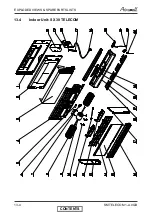
OPTIONAL ACCESSORIES
14-7
SM TELECOM 1-A.0 GB
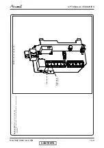
Installation Instruction for Electrical Heaters
( as shown on Kit )
Electric heating for
PXD 12 - 15 - 18 - 24 - 28 - 32
SX SP 9 - 12 - 15 - 18- -24 - 30
KIT DETAILS :
-
1
electric heater with wiring
-
2
metal su screws
-
2
screws to fix heater
-
1
foam insulation block
-
2
foam insulation squares
-
1
sticky back wiring diagram to place in the side panel above the unit
wiring diagram
-
1
configuration plug (heatpump = 243213 )
MAKE SURE THAT AIR CONDITIONER IS
DISCONNECTED FROM THE MAINS
KIT INSTALLATION :
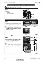
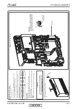
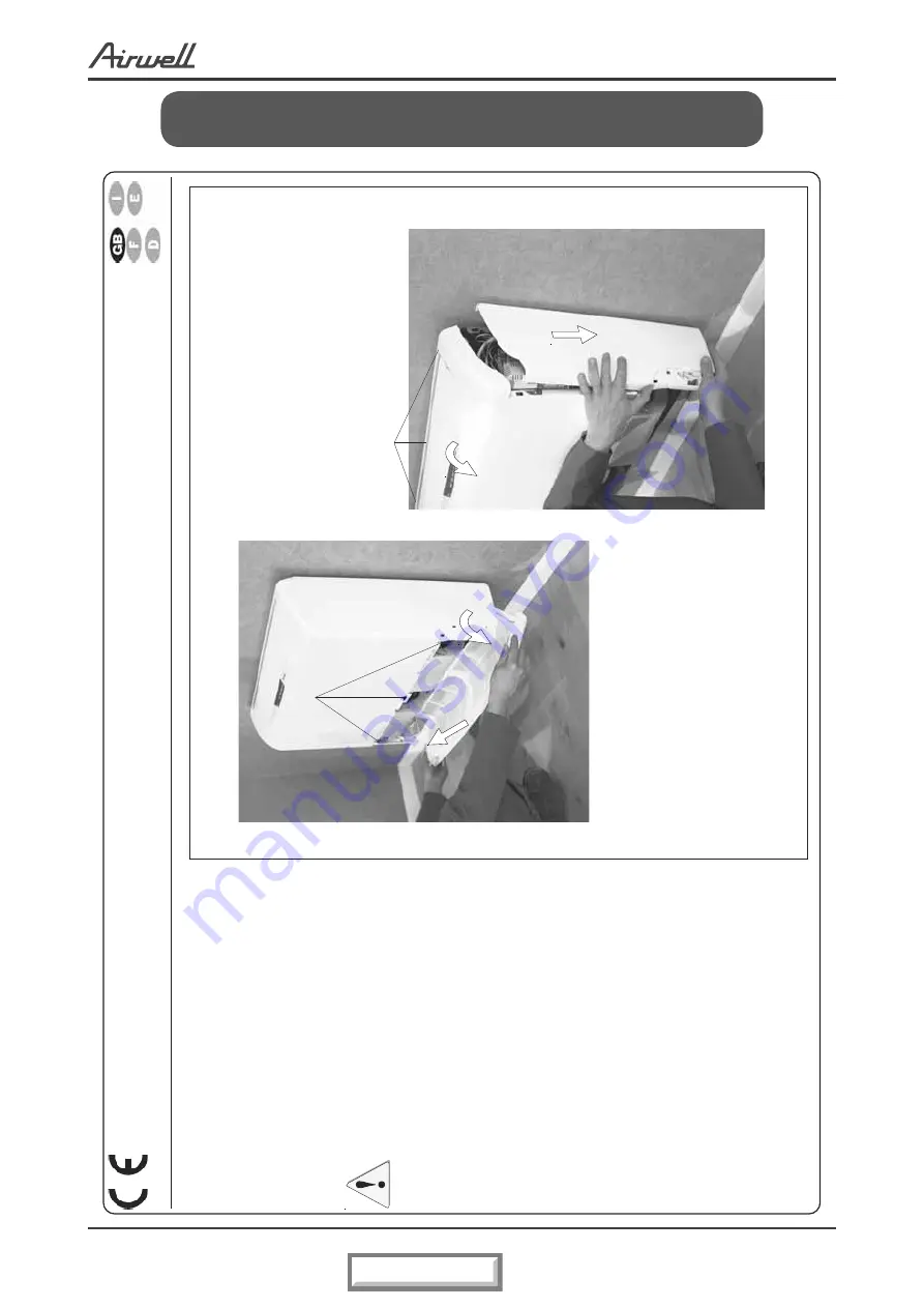
(Fig.1)
1
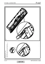
Open the return air grille by pulling both edges
2
Remove the end screws
Unscrew the middle screw without removing it
3
Unhook the grille by pulling upwards
4
Remove the side panels by pulling down
5
Remove the 3 screws holding the unit top
6
Unhook the unit top
Disconnect the wires between the
PXD
and the top:
•
Display cable (clear insulated cable).
•
Vertical louver motor wires (red and blue with connectors).
•
Horizontal louver motor wires (black).
Take care to separate the wire to help re-instalation.
Fig.1
1
2
3
4
5
6
TH 3263 E - 399529
CONTENTS
Summary of Contents for GC 12 LT
Page 13: ...OUTLINE DIMENSIONS 4 3 SM TELECOM 1 A 0 GB 4 5 Outdoor Unit GC 30T LT CONTENTS...
Page 28: ...CONTROL SYSTEM 11 3 SM TELECOM 1 A 0 GB 11 1 4 Main PCB Controller CONTENTS...
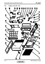
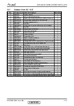
Page 70: ...EXPLODED VIEWS SPARE PARTS LISTS 13 6 SM TELECOM 1 A 0 GB 13 6 Outdoor Unit GC 12 LT CONTENTS...
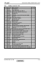
Page 72: ...EXPLODED VIEWS SPARE PARTS LISTS 13 8 SM TELECOM 1 A 0 GB 13 8 Outdoor Unit GC 18 LT CONTENTS...
Page 87: ...APPENDIX A 15 1 SM TELECOM 1 A 0 GB APPENDIX A INSTALLATION AND OPERATION MANUAL CONTENTS...

