OPTIONAL ACCESSORIES
14-8
SM TELECOM 1-A.0 GB
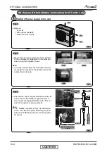
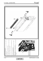
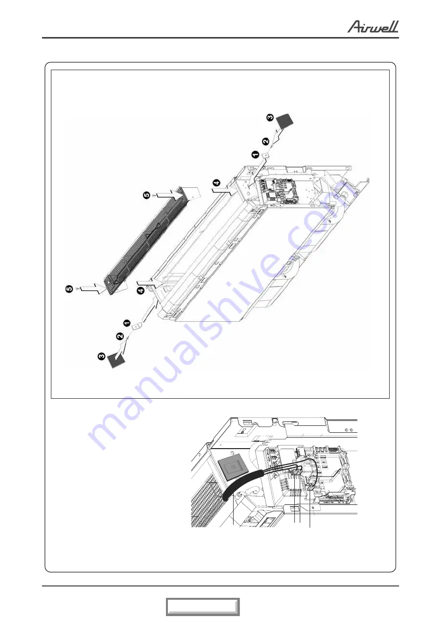
KIT INSTALLATION: (Fig.2)
1
Insert the metal support in the slots (push to break the polystyrene
behind the slot)
2
Fix the supports with the supplied screws
3
Cover the metal supports with the foam squares (to avoid air by-pass)
4
Slide the heater assembly into the PXD
5
Fix the heater assembly to the supports with the supplied screws
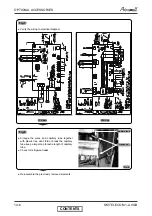
ELECTRICAL CONNECTIONS
-
Place the wiring in the corner so that the unit top can be replaced
MODELS PXD 12 - 15 - 18 - 24 - 28 - 32
-
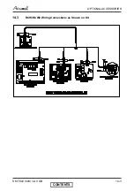
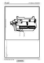
Connect the wires with 6.35 connectors directly to the control board
as shown
Fig.2
wiring
Violet wire to HE2
Black wire to HE1
Blue wire to N'1
CONTENTS
Summary of Contents for GC 12 LT
Page 13: ...OUTLINE DIMENSIONS 4 3 SM TELECOM 1 A 0 GB 4 5 Outdoor Unit GC 30T LT CONTENTS...
Page 28: ...CONTROL SYSTEM 11 3 SM TELECOM 1 A 0 GB 11 1 4 Main PCB Controller CONTENTS...
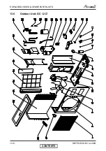
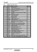
Page 70: ...EXPLODED VIEWS SPARE PARTS LISTS 13 6 SM TELECOM 1 A 0 GB 13 6 Outdoor Unit GC 12 LT CONTENTS...
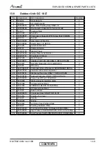
Page 72: ...EXPLODED VIEWS SPARE PARTS LISTS 13 8 SM TELECOM 1 A 0 GB 13 8 Outdoor Unit GC 18 LT CONTENTS...
Page 87: ...APPENDIX A 15 1 SM TELECOM 1 A 0 GB APPENDIX A INSTALLATION AND OPERATION MANUAL CONTENTS...


