59
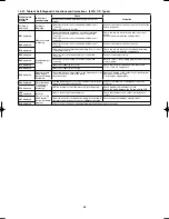
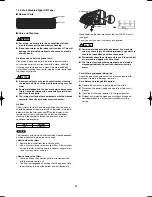
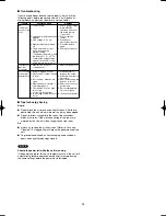
10-21. Table of Self-Diagnostic Functions and Corrections (4WK, C, D Types)
Wired remote
controller
display
Indoor unit
receiver lamp
Cause
Correction
Group connection and simultaneous-operation multi
system
Nothing is
displayed
Nothing is
displayed.
• Remote controller is not connected with indoor unit
correctly.
• Indoor unit power is not ON.
Connect the remote controller correctly. Turn ON the
indoor unit power.
E01
displayed
Operation lamp
is blinking.
• Automatic address setting has not been completed.
• Inter-unit control wiring is cut or is not connected
correctly.
• Remote controller is not connected with indoor unit
correctly.
Check the remote controller and inter-unit control
wiring.
Perform automatic address setting (10-22).
E02
displayed
• Remote controller is not connected with indoor unit
correctly.
Connect the remote controller correctly.
E14
displayed
• Remote controller communication wiring is cut or is not
connected correctly.
Check the remote controller communication wiring.
Perform automatic address setting again.
E04
displayed
Standby lamp is
blinking.
• Indoor-outdoor inter-unit wiring is not connected
correctly.
Connect the wiring correctly.
E06
displayed
• Inter-unit control wiring is cut or is not connected
correctly.
Refer to 10-22-1. Basic wiring diagram, and make the
correct setting.
E15
displayed
• Indoor unit capacity is too low.
Check that the total capacities of the indoor and
outdoor units are appropriate.
E16
displayed
• Indoor unit capacity is too high.
P05
displayed
Operation lamp
and Standby
lamp are blinking
alternately.
• Reversed phase or open phase in the 3-phase power at
one of the outdoor units in the group.
• Insuffi cient gas
Reverse 2 phases of the outdoor unit 3-phase power
and connect them correctly.
Fill up the gas appropriately.
P09
displayed
Timer lamp and
Standby lamp
are blinking
alternately.
• Ceiling panel connector at one of the indoor units in the
group is not connected correctly.
Connect the indoor unit ceiling panel connector
correctly.
P12
displayed
• DC fan trouble at one of the indoor units in the group.
Check whether the fan holder is loose.
Check the wiring between the DC fan and the PCB.
L02
L13
displayed
Both the
Operation lamp
and Standby
lamp are blinking
together.
• Indoor-outdoor unit type mismatch.
Check that the indoor and outdoor unit types are
correct.
L07
displayed
• Remote controller communication wiring is connected to
the indoor unit, however it is set for individual operation.
Perform automatic address setting (10-22).
L10
displayed
• Check outdoor operation with separate maintenance-use remote controller.
Airwell̲PAC-i̲eng.indb 59
Airwell̲PAC-i̲eng.indb 59
2009/07/09 16:13:42
2009/07/09 16:13:42
Summary of Contents for OU-PSINV-25HR
Page 75: ...75 ...

