43
Marvair Classic AVPA/HVPA/HVPSA Heat Pump I&O Manual
11/2017 Rev. 7
Ductwork must be firmly attached, secured and sealed to prevent air leakage. Do not use duct liner
on inside of supply duct within 4 feet (122 cm) of the unit. Galvanized metal duct extensions should
be used to simplify connections to duct work and grilles. Use fabric boots to prevent the transmission
of vibration through the duct system. The fabric must be U.L. rated to a minimum of 197°F (92°C).
WARNING
ELECTRICAL SHOCK HAZARD
Failure to follow safety warnings exactly could result in serious injury, death, and/or
property damage.
Turn off electrical power at fuse box or service panel BEFORE making any electrical
connections and ensure a proper ground connection is made before connecting line
voltage.
Heater installation (see drawings and wiring diagram)
1. Remove top front panel.
2. Remove bottom front panel.
3. Remove the control box cover.
4. Remove the heater access cover plate on the upper right side of the unit by removing the three
screws. Cut insulation on two sides and fold down out of way.
5. Slide new heater assembly into place by lining up stem with hole on far end. Make sure
stem of new heater assembly is inserted into correct hole. The hole nearest to the indoor coil
is for three element heaters and the farthest away from indoor coil is for all other heaters.
6. Install the two No. 10 screws in the heater assembly plate.
7. Install wire harness in hole provided in drain pan and then through filter bracket and then into
control box.
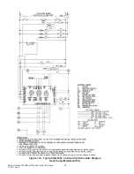
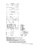
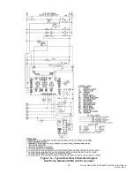
8. Wire the heater as shown in the wiring diagram provided with the heater kit (the insulated
terminal ends are to be connected at the heater).
9. Install pop tie in appropriate hole in back panel to secure wire.
10. Install closed cell strip around wires where they pass through the drain pan.
11. Reinstall the heater access cover.
12. Mount the heat contactor inside the control box where the mounting holes are provided for the
heat contactor.
13. Make the wiring connections inside the control box as shown in the wiring diagram provided
with the heater kit. Bundle loose wires with wire ties.
14. With a permanent marker, place an (X) in the space provided next to the heater kit rating of
the installed heater on the unit data label.
15. Place the wiring diagram provided with the heater kit inside the zip lock bag which is affixed
to the back side of the control box cover.
16. Replace the control box cover, the bottom front cover and the top front panel.

