5
C.
Make the duct connections at the furnace cabinet tight. Loose connections will
result in overheating of the component parts on the furnace and a reduction of
the heated air flow through the duct system.
D.
Avoid making any sharp turns in the flex duct system. Sharp turns will increase
the static pressure in the plenum area and could cause the furnace to cycle.
E.
Avoid making a lot of turns in the flex duct system. The straighter the duct
system, the better the performance of the furnace.
F.
When using flex duct, insure the duct is stretched and routed straight. Do not
use longer length of flex duct than is needed to route directly from furnace to
register. Do not allow the duct to kink or accumulate.
G.
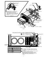
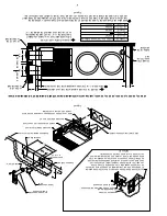
Maintain a minimum of 1/4” clearance where ducts pass through any
combustible construction, such as coach cabinetry. (See Figure 1.)
NOTE
: UL
listed duct materials can be 0” clearance.
H.
Do not install air boosters in the duct system. Such devices will cause the
furnace to cycle on limit and to have erratic sail switch operation.
NOTE:
After installation of the furnace and duct system is completed, adjustments
must be made to obtain a temperature rise within the range specified on the Rating
Plate.
INSTALLING THERMOSTAT
The thermostat used with this unit must have NO voltage output to return leg when
there is not a call for heat or in the “OFF” setting.
Locate the room thermostat approximately 4-1/2 feet above the floor on an inside
bulkhead where it is not affected by heat from any source except room air. Connect
thermostat wiring to the blue wire and blue-white striped wire (blue-white striped
wire is power to the thermostat) on right side of furnace. (See wiring diagram.) If
your furnace is equipped with a thermostat that has an adjustable anticipator, the
anticipator should be set at .7 amps. If you desire longer heating cycles, adjust
the anticipator to a higher setting. If you desire shorter heating cycles, adjust the
anticipator to a lower setting. Adjustments to the anticipator setting should be made
in .5 amp increments.
PREVENTIVE MAINTENANCE
WARNING
If the user of this appliance fails to maintain it
in the condition in which it was shipped from
the factory or if the appliance is not used solely
for its intended purpose or if appliance is not
maintained in accordance with the instructions
in this manual, then the risk of a fire and/or the
production of carbon monoxide exists which
can cause personal injury, property damage or
loss of life.
CAUTION
Label all wires prior to disconnecting for servicing and
servicing controls. Wiring errors can cause improper and
dangerous furnace operation. Proper polarity MUST BE
OBSERVED so the furnace motor will run with the proper
direction of rotation to insure correct air delivery. (See
wiring diagram).
Always verify proper operation of furnace after servicing.
Your furnace should be inspected by a qualified service agency yearly before turning
the furnace on. Particular attention should be given to the following items.
1.
Inspect furnace installation and vent termination to be sure furnace is properly
secured in place (see Installation Instructions), that vent terminates to the
atmosphere, and that vent tubes overlap properly (see Installing Vent Assembly.)
2.
Inspect chamber and venting to assure that these components are physically
sound without holes or excessive corrosion and that the installation and/
or re-installation is in accordance with Suburban’s installation instructions.
(Reference installation manual supplied with furnace.)
WARNING
It is imperative that the products of combustion
be properly vented to atmosphere and that all
combustion air supplied to burner be drawn
from outside atmosphere.
3.
Check the base on which furnace is mounted. Be sure it is physically sound,
void of any sagging, deterioration, etc.
4.
Inspect furnace, the venting, ducting and gas piping to furnace for obvious
signs of deterioration. Correct any defects at once.
5.
Inspect combustion chamber for restrictions in exhaust or intake. It is imperative
that the flow of intake combustion air and the flow of exhaust gases being
expelled to the outside atmosphere not be obstructed. Any soot or loose debris
should be blown out using compressed air. (See Figure 8.)
6.
Inspect all gaskets. If any gaskets show signs of leakage or deterioration, replace
them. Safe operation of the furnace depends on all gaskets being tight.
7.
Inspect return air inlet openings to the furnace. Remove any restrictions to
assure adequate air flow.
You, as the owner/user, should inspect the furnace monthly during the
heating season for presence of soot on vent. Operating the furnace under this
condition could lead to serious property damage, personal injury or loss of life.
If soot is observed on the vent, immediately shut the furnace down and contact
a qualified service agency.
Listed below are several safety related items that you should follow during the
heating season to assure continued safe operation of the furnace.
1.
Inspect furnace venting. Venting must be free of obstructions, void of soot, and
properly terminated to the atmosphere. (See Installing Vent Assembly.)
WARNING
Do not install screens over the vent for any
reason. Screens will become restricted and
cause unsafe furnace operation. Accessories
are being marketed for RV products which we
do not recommend. For your safety, only factory
authorized parts are to be used on your furnace.
2.
Periodically inspect the vent for obstructions or presence of soot. Soot is
formed whenever combustion is incomplete. This is your visual warning that
the furnace is operating in an unsafe manner. If soot is present, immediately
shut furnace down and contact your dealer or a qualified service person.
3.
Keep furnace clean. More frequent cleaning may be required due to excessive lint
from carpeting, bedding material, etc. It is imperative that control compartments,
burners and circulating air passageways of the appliance be kept clean.
4.
The motor is permanently lubricated and requires no oiling.
5.
Keep the furnace area clear of any combustible materials, gasoline or other
flammable vapor and liquids.
6.
Before operating furnace, check the location of the furnace vent to make sure it
will not be blocked by the opening of any door on the trailer. If it can be blocked,
do not operate the furnace with the door open.
7.
Do not restrict the flow of combustion air or the warm air circulation to the
furnace. To do so could cause personal injury and/or death.
8.
Never operate the furnace if you smell gas. Do not assume that the smell of
gas is normal. Any time you detect the odor of gas, it is to be considered life
threatening and corrected immediately. Extinguish any open flames including
cigarettes and evacuate all persons from the vehicle. Shut off gas supply at
Propane gas bottle. (See safety notice on front cover of this manual.)
9.
Immediately shut furnace down and call a service agency if furnace cycles
erratically or delays on ignition.
WARNING
Should overheating occur, or the gas supply
fail to shut off, shut off the manual gas valve to
the appliance before shutting off the electrical
supply.
10.
Never attempt to repair damaged parts. Always have them replaced by a
qualified service agency.
11.
Never attempt to repair the furnace yourself. Seek the help of a qualified
service person.
12.
Never restrict the ducting installed by your trailer manufacturer. To do so could
cause improper furnace operation.
13.
Do not install air boosters in the duct system. Such devices will cause the
furnace to cycle and to have erratic sail switch operation.
14.
Clothing or other flammable material should not be placed on or near the
appliance.
15.
Always follow the operating instructions. Do not deviate from the step-by-step
procedures.
16.
Do not use this appliance if any part has been submerged under water.
Immediately call a qualified service technician to inspect the appliance and
to replace any part of the control system and any gas control that has been
submerged under water.
17.
When considering add-on rooms, porch or patio, attention must be given to the
venting of your furnace. For your safety, do not terminate furnace vent inside
add-on rooms, screen porch or onto patios. Doing so will result in products of
combustion being vented into the room or occupied areas.


