


14
EN
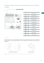
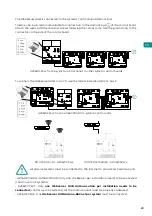
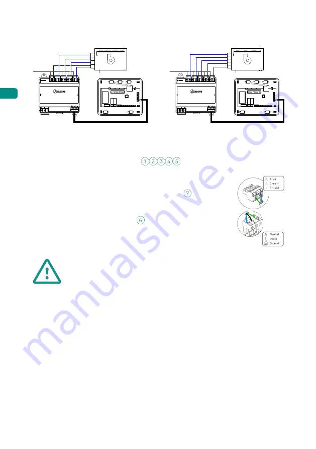
4-pipe installation
F-Coil
N
L
V1
V2
Y
V3
W
W
V3
Y
O
V1
V2
O
O
O
O
2-pipe installation
Connection
F-Coil
V1
W
V3
Y
O
V1
V2
O
O
O
O
V2
V3
W-Y
N
L
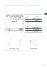
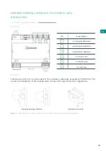
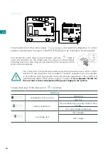
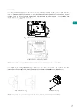
For connection to the main control board AC unit bus
there is one
4-pin terminal. Fix the cables with the screws on the terminal, following
the color code. Only use the shield on the connector on the main control
board side.
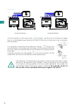
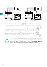
The power connection to the module
is via a 3-pin terminal. Fix the
cables with the screws on the terminal, following the polarity.
The connection to the external power supply must include a main switch or other
method of disconnection that includes a constant separation for all polarities,
in accordance with appropriate local and national regulations. The system will
automatically restart if the power supply is turned off.
Use separate circuits for
the unit that is to be controlled and the power supply to the system.
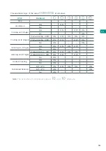
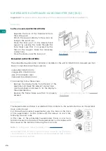
The characteristics of the control relays are Imax 10 A at 110/230 VAC voltage
free. To control higher power elements, the use of contactors of the power to be controlled is
recommended.


