


26
EN
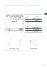
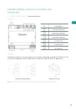
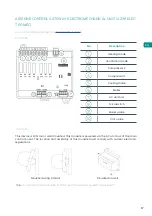
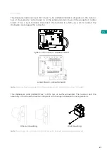
Connection
Digital inputs
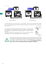
Automation bus
The production control board is equipped with 4 digital inputs for external control of Airzone
systems. These inputs are configured as normally open. For connection, the use of shielded
cable is recommended.
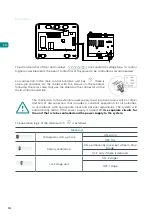
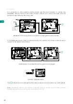
DHW: This input activates the DHW mode, whereby all Acuazone/Innobus Pro32 and Flexa
4.0 systems that are working in air heating will stop and display the DHW message on the
zone thermostats. This function is recommended for air to water installations when the air
to water unit starts to produce DHW for the production of heating and air conditioning.
HEATING: This input activates the semi-forced heating mode in all the systems in the
installation. It allows the selection of the modes: Stop, Heating and Ventilation.
COOLING: This input activates the semi-forced cooling mode in all the systems in the
installation. It allows the selection of the modes: Stop, Cooling, Dry and Ventilation.
STOP: This input activates the Stop mode in all the systems in the installation.
PROBE: The main control board has an analogue input for connecting a temperature
probe to protect the boiler.
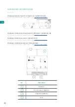
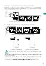
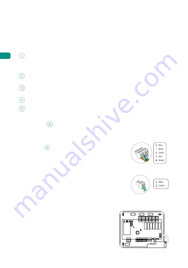
The automation bus allows several systems to be interconnected in order to manage all of
them, using the control peripherals offered by Airzone or their integration into a higher-level
control network.
To connect the
automation bus, there are two 5-pin terminals.
This system only uses bus connections. Fix the cables with the
screws on the terminal, following the color code.
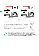
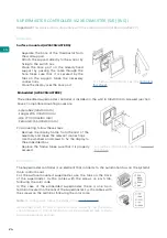
The indoor automation bus allows the production control board
to be interconnected with the system main control board. For the
connection of the indoor automation bus, it has one 2-pin terminal.
This system only uses bus connections. Fix the cables with the
screws on the terminal, following the color code.
In the case of the Airzone Cloud Webserver connection,
remove the Webserver fixing post and fit the connector on
the outdoor home automation bus (only for AZAX6CCP).
Note:
Remember that, for this main control board to work correctly, all the main control
boards in the installation must be addressed (up to 32 systems) (see System advanced settings
section).
Note:
For elements with external power supply at 110/230 VAC, it is
only necessary to connect poles "A" and "B" of the automation bus.
ON
1 2


