6
GENERAL RECOMMENDATIONS
Before starting the commissioning, please follow these recommendations:
•
Address the zoning system before the commissioning from ETS to integrate it with the KNX devices available in the
network.
•
Do not associate communication devices that won’t be used in the KNX project. The number of associations is
limited to 247.
•
Configure the device parameters by selecting the topology of the used system and select the corresponding values
for the device parameters used in the system.
•
If there is any zone without an Airzone thermostat, to control the zone from a KNX device, previously configure the
zone from the KNX control device or from the group address monitor. This configuration is important to control the
zones in water installations (to access a zone, it must have at least a valid Airzone address).
•
If there is more than one system and these systems are connected to VRF units, it is essential to group the mode
changeover communication objects at the same group address.
•
If you do not have Airzone thermostats in the installation, it is important to:
o
To indicate the flag switch in the OC of local temperature.
o
Report the room temperature of each zone every 5 minutes or less. Otherwise, the main control board will
remove the zone and you will not be able to control it.
o
After downloading the application program or after a power failure of the system, it is necessary to send
all communication objects that are being used (Room T, Set-point temp, On/Off, Mode, Stage, etc.).
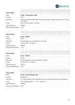
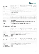
CONFIGURATION PARAMETERS
The configurable parameters are related to the communication objects available for the KNX-Airzone gateway. They are
visible in the device database for the ETS software tool depending on the system configuration and the available zones. The
value of each parameter is selected during the setup process, based on the peripherals connected to the system.
To control the AC system through KNX it is necessary to select the proper system topology, because this parameter affects
the rest of parameters, as the number of available zones or the selection of some communication characteristic objects of
each technology.
The representation of the system communication objects will be displayed in the ETS tool according to the values assigned
to the parameters during the device configuration and setting up, changing the system and zone configuration.
The commissioning starts by selecting the values of the System parameters.
•
System topology:
Allows you to select the topology of the system. It is configured as
centralized
by default, so the
available communication objects will be displayed.
Remember:
Depending on the selected topology, the communication objects related to this mentioned topology will be
displayed. Modify the topology anytime considering that this parameter is the most influential for the commissioning.
•
System model:
Allows you to select the model of the system.
FLEXA 3 system
is selected by default, which means
that the communication objects which are not available for this system will not be visible.
•
Type of installation:
Determines the type of installation. These are the available options:
Inverter (A/A) - Fan Coil
(F/C)
(by default),
2-pipe installation, 4-pipe installation
and
mixed
.
When you configure it as Inverter (A/A) - Fancoil (F/C), you also have to select the Unit gateway type: Inverter
unit gateway (A/A) or Fancoil unit gateway.
If you configure it as 2-pipe or 4-pipe installation, the Ventilation speed per zone will be available
if the zone is
controlled by a Fancoil module.
If it is configured as
4-pipe installation
, you can select, in addition, the value of the operation mode of the AC unit
by enabling the
Zone operation mode.
•
Radiant elements module.
Allows you to enable/disable the control module of radiant elements connected to the
system. It is
Not connected
by default. If you enable this parameter, you will see a sub-menu where you can enable
all the control modules of radiant elements connected to the system.

