11
5.2 Wiring recommendations
Previous to the wiring lay out, draw a plan schematic, where the thermostats will be located,
and then where the dampers will be installed.
Based on the wiring lay out diagram, the cable can be laid out starting from where the Airzone
Controller will be installed, (normally next to the AHU or furnace), and from there to the closest
damper, and thus following to the other dampers in the System.
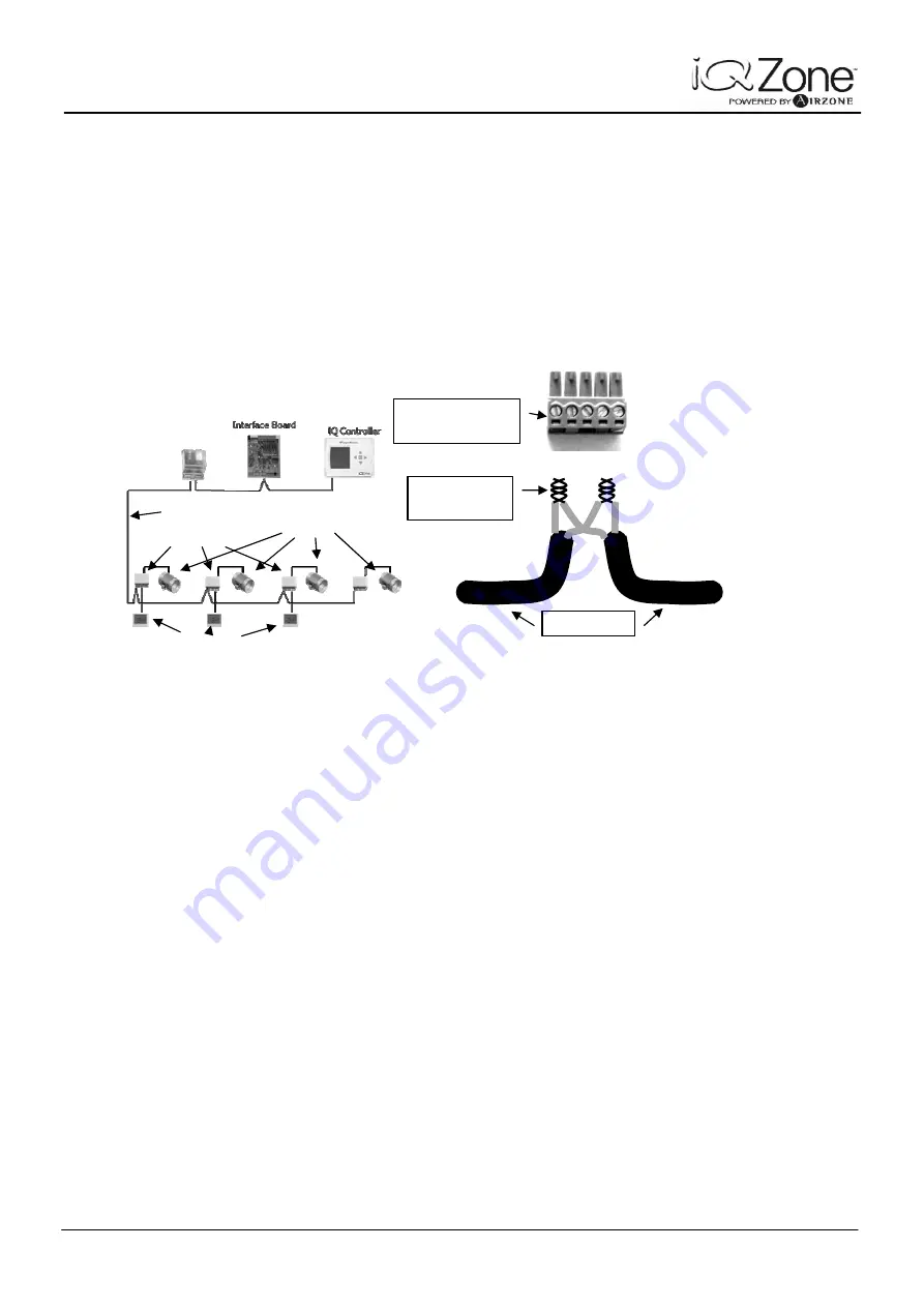
Please, see below a typical wiring lay out and Daisy chain connection.
Fig. 3
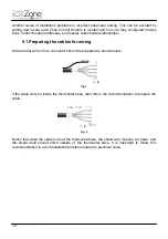
As mentioned before, shielding is an important factor in the wiring, and it has to be correctly
done. Always keep this in mind:
a) The shield will be connected only to one connector in the system, and that will be the
ground connector in the Airzone Controller
b) At the Zone Control Modules, the shields of inbound and outbound communication
cables, and the thermostat cable will be connected together, and isolated. Do not
connect the shield to the Zone Control Module Connector.
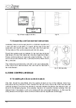
The cable that connects the thermostat with the Zone Control Module should not exceed 45 ft.
Exceeding this length will cause zone operation malfunction.
There may be situations where the distance between the Thermostat and the associated Zone
Control Module is more than 45ft. In cases like this, the Zone Control Module can be installed in
some place closer to the thermostat. Obviously, such action will require an extension of the
Damper motor cable. If the damper motor cable needs to be extended, AWG 18 bicolor cable is
required. Be extremely careful to keep the color code when extending the motor cable. The
Zone Control Module has engraved in the box “M+” and “M-“ showing where the red and black
cables must be connected. If proper polarity is not followed, the damper will close when it
should open and vice versa.
Airzone Controller
Zone Controllers
Dampers
Thermostats
Bus Cable
Daisy Chain
Connection
Zone Controller
Bus Connector
Bus Cable
Summary of Contents for iQ Zone
Page 1: ...Installation Manual...
Page 2: ......
Page 5: ......
Page 17: ...17 Fig 12 Fig 13 Fig 14...
Page 43: ......
Page 44: ......
Page 45: ......

