12
Fig. 4
6. AIRZONE CONTROLLER
6.1 Description and Configuration
The Airzone controller has several inputs and outputs as shown below:
Fig. 5
6.2 Connecting the Airzone Controller
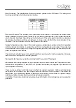
12VDC. The Airzone Controller must be connected to an Airzone Supplied Power Supply. The
power supply can be connected to any voltage between 100 VAC and 240 VAC.
Set Configuration Push Button. Once all modules are configured and there are no errors
detected, the installer must press this button to save the configuration table in the Airzone
Controller. The button must be kept pressed while the IQ Bus Activity/Configuration LEDs stay
ON (please, see below IQ Bus Activity/Configuration LEDs).
iQ Link. The cable that connects to the A and B wires in the iQ Interface Board (in the AHU or
furnace), must be connected to the A and B terminals of the three pin connector. A and B
identification is labeled above the Airzone Controller PC board.
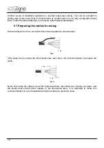
Airzone Controller
Zone Controller
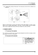
Shield
wires
Bus
Cable
Thermostat
Cable
Summary of Contents for iQ Zone
Page 1: ...Installation Manual...
Page 2: ......
Page 5: ......
Page 17: ...17 Fig 12 Fig 13 Fig 14...
Page 43: ......
Page 44: ......
Page 45: ......

