14
Fig.6
Power LED. This is a red LED that will be ON all time the power supply is connected and active.
Mode LEDs. This set of LEDs provides indication of which mode the IQ Controller has the AC
unit working. These are the assignments:
D4: Stop/OFF
D5: Cool
D6: Heat
D7: System Wide Ventilation
D8: Zone Ventilation
D9: Start Bit ON
Bus Activity LEDs. This is a set of green/red LEDs. When the bus is running normally, both will
be blinking. If only one is blinking (red), then it means that the bus is not connected to the Zone
Control Modules.
iQ Bus Activity/Configuration LEDs. In normal operation, this set of green/red LEDs blinking,
indicates that the Airzone Controller is communicating with the iQ Controller. During the process
of saving the configuration setup, the LEDs will be ON while receiving information from the Zone
Control modules, and will return to OFF once the configuration is saved.
6.3 Installation
The Airzone Controller must be installed mounted on a DIN rail, provided together with the
controller, and next to the AHU or furnace.
To install the controller:
1)
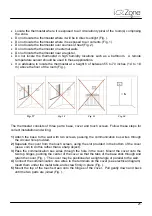
Attach the DIN rail to a firm surface near the air handler or furnace (Fig. ).
2)
Place the upper part of the controller (with the power supply receptacle at the upper left)
on the upper edge of the rail.
3)
Using a screwdriver,
gently
pull downward on the release tab (at the center of the lower
edge of the controller) and snap the controller onto the lower edge of the rail.
Microswitch bank
Jumper J2
Mode LEDs
Power LED
Bus Activity LEDs
iQ Bus Activity /
Configuration LEDs
Summary of Contents for iQ Zone
Page 1: ...Installation Manual...
Page 2: ......
Page 5: ......
Page 17: ...17 Fig 12 Fig 13 Fig 14...
Page 43: ......
Page 44: ......
Page 45: ......

