15
4)
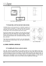
To disassemble,
gently
pull downward on the release tab, and remove the controller from
the DIN rail.
Fig. 7
Fig. 8
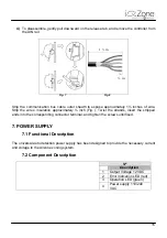
Strip the communication bus cable outer sheath to expose approximately 1½ inches of wire.
Strip the wires’ insulation approximately ¼ inch (Fig. ). Twist the strands, insert the stripped
ends into the corresponding connector terminal, and tighten the screws until fixed.
7. POWER SUPPLY
7.1 Functional Description
The universal auto detection power supply has been designed to provide the necessary current
and voltage to the Airzone zoning system.
7.2 Component Description
Nº
Description
1
Output Voltage 12 VDC
2
Error indication LED (red)
3
Operation LED (green)
4
Power supply 110/240
VAC
1 ½ in
¼ in
Summary of Contents for iQ Zone
Page 1: ...Installation Manual...
Page 2: ......
Page 5: ......
Page 17: ...17 Fig 12 Fig 13 Fig 14...
Page 43: ......
Page 44: ......
Page 45: ......

