21
•
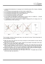
Locate the thermostat where it is exposed to air circulation typical of the room(s) comprising
the zone.
•
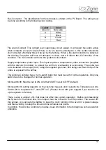
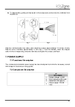
Do not locate the thermostat where it will be in direct sunlight (Fig. ).
•
Do not locate the thermostat where it is exposed to air currents. (Fig. 1).
•
Do not locate the thermostat over sources of heat (Fig. 2).
•
Do not locate the thermostat on external walls.
•
Do not locate the thermostat near a register.
•
Do not locate the thermostat in high humidity locations such as a bathroom. A remote
temperature sensor should be used in these applications.
•
It is advisable to locate the thermostat at a height h of between 55 to 70 inches (1.4 to 1.8
m) above the floor of the room (Fig. ).
Fig. 17
Fig. 18
Fig. 29
Fig. 20
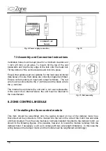
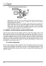
The thermostat consists of three parts: base, cover and touch screen. Follow these steps for
correct installation and wiring:
1)
Attach the base to the wall with two screws, passing the communication bus wires through
the circular hole provided.
2)
Separate the cover from the touch screen, using the slot provided in the bottom of the cover
(use a coin to do this rather than a sharp object).
3)
Pass the communication bus wires through the hole in the cover. Mount the cover onto the
two top hinges, pushing the center of the cover so that the tabs of the base stick through and
retain the cover (Fig. ). The cover may be positioned at a slight angle or parallel to the wall.
4)
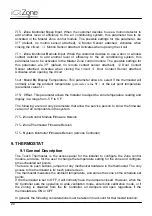
Connect the communication -bus wires to the terminals on the cover (see electrical diagram).
Insert them under the metal tabs, and screw firmly in place (Fig. ).
5)
Mount the top of the touch screen onto the hinges of the cover. Pull gently down and back
until the two parts are joined (Fig. ).
h
Summary of Contents for iQ Zone
Page 1: ...Installation Manual...
Page 2: ......
Page 5: ......
Page 17: ...17 Fig 12 Fig 13 Fig 14...
Page 43: ......
Page 44: ......
Page 45: ......

