37
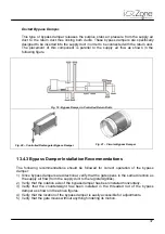
Ducted Bypass Damper.
This type of bypass damper releases the surplus static air pressure from the supply air
duct to the return duct thus linking both ducts. These bypass dampers are specifically
designed to be inserted into the supply duct in order to be connected with the return duct.
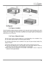
The placement of this component is parallel to the supply air flow as shown in the
following figure
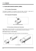
Fig. 19 - Bypass Damper in Controlled Return Ducts
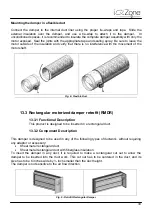
Fig. 20 – Controlled Rectangular Bypass Damper
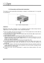
Fig. 21 – Circular Bypass Damper
13.4.3 Bypass Damper Installation Recommendations
The following recommendations should be followed for correct operation of the bypass
damper:
1) Since bypass dampers are directional, verify that the gate opens in the same direction as
the supply air flow (from the supply duct to the registers/grilles).
2) Verify that the rotation axle of the bypass damper has been installed horizontally.
3) Verify that the counterweight has been installed in the threaded rod of the bypass
damper as shown in the above figures.
4) Verify that the location of the bypass damper is easily accessible for adjustments.
5) Verify that the gate moves without anything hindering its motion.
Summary of Contents for iQ Zone
Page 1: ...Installation Manual...
Page 2: ......
Page 5: ......
Page 17: ...17 Fig 12 Fig 13 Fig 14...
Page 43: ......
Page 44: ......
Page 45: ......


