23
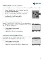
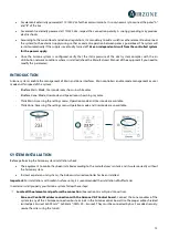
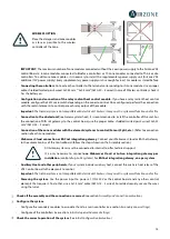
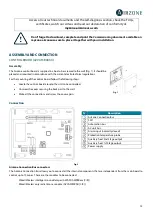
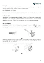
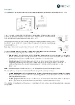
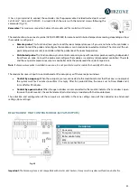
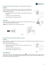
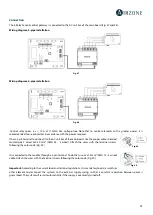
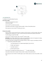
It has a 4-pin terminal to connect the controller. Use the proper cable: shielded twisted pair 4 wired:
2x0.22 mm
2 +
2x0.5mm
2
(AWG 20 – 4 wired). Attach the wires with the terminal screws following the
color code (Fig. 24).
Remember:
The maximum separation between the module and the controller is 10 meters.
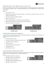
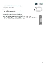
The module allows to connect a probe (AZVAF10KPROBE) for remote or distributed temperature reading, depending on how
the module is configured:
•
Remote probe:
This function allows you to read the room temperature even if you are not where the controller is
located. Connect the probe and configure the module as main module (connected controller). The state and the set-
point temperature are set via controller while the probe reads the room temperature.
•
Distributed probe:
This function allows you to control a secondary zone with room temperature reading independent
from the main zone. Connect the probe and configure the module as secondary (disconnected controller). The state
and the set-point temperature are set via controller while the probe reads the room temperature.
Note:
If a temperature probe is installed in one zone, it is not possible to read or control the humidity of that zone.
The module has several inputs to control based on the occupancy or if there are open windows.
•
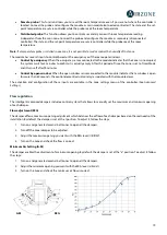
Control by occupancy:
When the occupancy sensor connected to the module indicates that the zone is unoccupied,
the system waits for 5 minutes to confirm it is empty. After this period of time, the zone is set to Timer Mode and it
turns off after 90 minutes.
•
Control by open window:
When the open window sensor connected to the module indicates that a window is open
for more than 60 seconds, the control element (actuator/relay) associated with that module closes.
The activation and configuration of these inputs are available in the zone settings menu of the controller (see Advanced
settings, Zone settings).
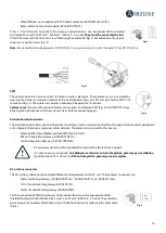
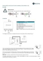
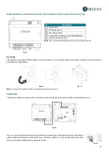
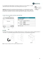
RELAY RADIANT HEAT CONTROL MODULE (AZVAF5OUTPUTS)
Important:
The Airzone system is not compatible with electric duct heaters, it may result in system malfunction and/or fire.
Fig. 25
N˚
Description
Zone relay
Pump control relay
Boiler control relay
SW2
Airzone connection bus
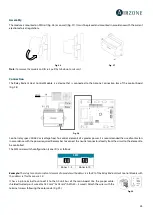
Fig. 24

