28
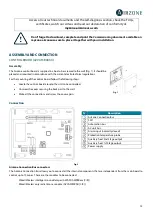
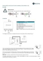
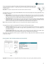
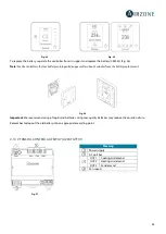
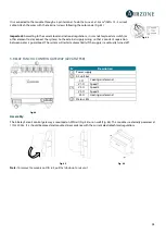
It is connected to the module through a 3-pin terminal. To do that, use a 3x1.5 mm² (AWG 15 – 3 wired)
cable. Attach the wires with the terminal screws following the color code (Fig. 43).
Important:
According to the current local and national regulations, it is mandatory to add a switch (or
other element to disconnect the system) to the external supply wiring so that a constant separation
between poles is guaranteed. The system will restart automatically if the supply is eventually turned off.
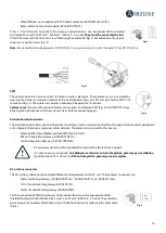
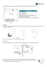
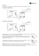
5-RELAY FANCOIL CONTROL GATEWAY (AZVAFGTF5R)
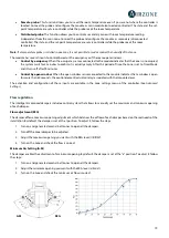
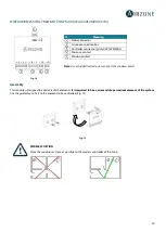
Fig. 44
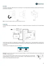
Assembly
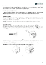
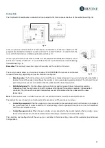
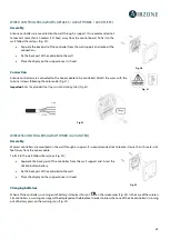
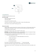
The 5-Relay Fancoil control gateway is mounted on DIN rail (Fig. 45) or on wall (Fig. 46). This module is externally powered at
110/230 Vac. It is should be placed and mounted in accordance with the current electrotechnical regulations.
Fig. 45
Fig. 46
Note:
To remove the module on DIN rail, pull the tab down to release it.
N˚
Description
Power supply
AC unit bus
Y-O
Cooling air demand
V1-O
Speed 1
V2-O
Speed 2
V3-O
Speed 3
W-O
Heating air demand
Status LEDs
Fig. 43

