background image


31 


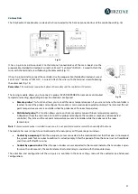
Fig. 54 

Note:

 For a proper operation of this module, all the control boards must be addressed (see section Advanced Settings, System ID 

parameter). 


Configuration 

To configure it, follow the steps described in the Airzone Cloud Webserver installation manual, available at 
myzone.airzoneusa.com.


BACNET INTEGRATION GATEWAY (AZVAFBACNETG) 


All Airzone systems must be connected to internet to offer technical support. 

It is only necessary to connect 

one BACnet integration gateway per system

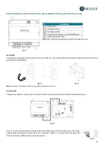
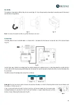
Assembly 

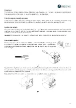
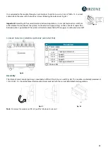
The BACnet integration gateway is integrated into the automation bus of the main board (Fig. 56). It has a 5-pin terminal, 
disconnect the terminal and insert the connector. 


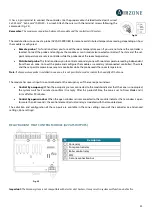
Configuration 

To configure it, follow the steps described in the installation manual, available at myzone.airzoneusa.com.


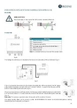
AZVAFWSCLOUDR 


N˚ 

Description 

  Ethernet 
  Automation bus output 
  Automation bus input 


Fig. 55 


Fig. 56 


Fig. 57 


Summary of Contents for VAF AZVAFCB Series

Page 1: ...r e b m u N e g a P d r a o b p il C Installation Manual...

Page 2: ......

Page 3: ...l Gateway AZVAFGTF5R 9 Webserver Airzone Cloud Ethernet WiFi AZVAFWSCLOUD C R 10 Bacnet Integration Gateway AZVAFBACNETG 10 Lutron Integration Gateway AZVAFLUTRONG 10 10 KOHM NTC Thermistor AZVAF10KPR...

Page 4: ...3 Blueface and Think controllers 33 Lite controllers 36 Lite controller reset 37 Initital configuration evaluation 37 User and zone settings 38 Blueface Controller 38 User Settings 38 Zone Settings 38...

Page 5: ...f they are not handled appropriately The symbol of a crossed out waste bin indicates that electrical equipment should be collected separately from other urban waste For correct environmental managemen...

Page 6: ...it may result in system malfunction and or fire WIRED WIRELESS INTELLIGENT ROUND DAMPER AZVAFDAMPERXX C R Damper with actuator Damper with actuator of 6 8 10 12 or 14 inch diameter Powered with 12 VDC...

Page 7: ...of Pump Demand Relay of Boiler Identified by means of a micro switch Important The Airzone system is not compatible with electric duct heaters it may result in system malfunction and or fire BLUEFACE...

Page 8: ...mperature of the zones in Airzone systems Wired wireless communication Powered by zone module wired or by battery button CR2450 wireless Features On off of the zone Set point temperature control accur...

Page 9: ...the unit 0 10 V FANCOIL CONTROL GATEWAY AZVAFGTF10 Control gateway of air to water zoning units Fan control through 0 10 V output and opening closing electrovalves Compatible with 2 pipe and 4 pipe in...

Page 10: ...INTEGRATION GATEWAY AZVAFBACNETG Integration gateway for controlling Airzone installations through BACnet platform Connected to router via Ethernet Power supplied through the control board automation...

Page 11: ...ing Protection probe for air supply ADDITIONAL 12 V POWER SUPPLY AZVAFPOWER External power supply for Airzone system DIN rail mounted 110 230 Vac power supply Power supply for more than 6 zone modules...

Page 12: ...ated area to maintain the actuator of the damper outside it Once finished check the tightness of the joints between the damper and the duct On zones controlled by wireless controllers place the damper...

Page 13: ...eed of the system Blueface Main Mode User mode icons shown in white color Blueface Zone Mode User mode and Speed icons shown in gray color Think Main Accessing the settings menu Operation mode and Use...

Page 14: ...ne modules with the elements systems to control Fancoil Split etc Refer to connection section of each zone module Webserver Cloud connection or BACnet integration gateway Connect your Webserver Cloud...

Page 15: ...ing of the control board follow the following steps Locate the control board close to the unit to be controlled Unscrew the cover securing the back part to the wall Make all the connections and screw...

Page 16: ...n Automation bus connector The automation bus allows you to interconnect multiple systems in order to control them through Airzone control peripherals or to integrate them into a superior control netw...

Page 17: ...is recommended to use contactors in accordance with the power required Important The Airzone system is not compatible with electric duct heaters it may result in system malfunction and or fire Power s...

Page 18: ...ded twisted pair 4 wired 2x0 22 mm2 2x0 5mm2 AWG 20 4 wired Attach the wires with the terminal screws following the color code Fig 13 Remember The maximum separation between the module and the control...

Page 19: ...Control by open window When the open window sensor connected to the module indicates that a window is open for more than 60 seconds the control element actuator relay associated with that module clos...

Page 20: ...of the system Use the guideway to fix it to the element to be controlled Fig 15 Fig 15 Fig 14 N Meaning Probe connector Airzone connection bus Controller connection Only AZVAFZMRADC Presence contact...

Page 21: ...set point temperature are set via controller while the probe reads the room temperature Distributed probe This function allows you to control a secondary zone with room temperature reading independen...

Page 22: ...e is a device that is connected to the Airzone connection bus of the control board Fig 22 It has a 5 pin terminal to connect it to the Airzone Connection Bus of the main board Use the proper cable shi...

Page 23: ...et point temperature are set via controller while the probe reads the room temperature Note If a temperature probe is installed in one zone it is not possible to read or control the humidity of that z...

Page 24: ...s recommended the use of contactors in accordance with the power required Remember to connect the neutral connector directly from the circuit to the element to be controlled The SW2 microswitch config...

Page 25: ...tool to press in the locking tabs Fig 32 WIRELESS CONTROLLERS AZVAFTHINKR AZVAFLITER Assembly Wireless controllers are mounted on the wall through a support It is recommended not to locate it more th...

Page 26: ...out 5 minutes from the battery replacement Fig 36 Important We recommend using of top brand batteries Using low quality batteries may reduce the duration of use Remember to deposit the old battery int...

Page 27: ...nnected to the AC unit bus of the main board Fig 40 and 41 Wiring diagram 2 pipe installation Fig 40 Wiring diagram 4 pipe installation Fig 41 Control relay specs Imax 10 A at 110 230 Vac voltage free...

Page 28: ...ranteed The system will restart automatically if the supply is eventually turned off 5 RELAY FANCOIL CONTROL GATEWAY AZVAFGTF5R Fig 44 Assembly The 5 Relay Fancoil control gateway is mounted on DIN ra...

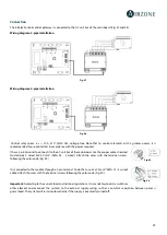
Page 29: ...oard Use the proper cable shielded twisted pair 2 wired 2x0 22 mm2 AWG 24 2 wired Attach the wires with the terminal screws following the color code Fig 49 It is connected to the module through a 3 pi...

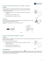
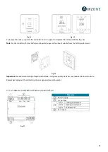
Page 30: ...52 It has a 5 pin terminal Disconnect the terminal and fit the connector Connection To connect with other system s main boards Fig 54 use the 2 pin terminal to connect the Webserver Cloud to the auto...

Page 31: ...e systems must be connected to internet to offer technical support It is only necessary to connect one BACnet integration gateway per system Assembly The BACnet integration gateway is integrated into...

Page 32: ...ION Check the following aspects The state of the LEDs of the control board and the rest of control elements Check the self diagnose section of the data sheet of the elements All controllers are powere...

Page 33: ...he different wireless zone modules found with the signal level of each one of them Select the wanted module and press Check the selected module will begin to beep to be identified Verify the range is...

Page 34: ...unit Main ID only if the controller has been previously configured as zone Select the main controller zone ID associated to the controller Thus this main controller will impose the operation mode to...

Page 35: ...35 Think Important In Think controllers use to confirm and to return to the previous screen or menu...

Page 36: ...n the wireless search The LED will blink in green IMPORTANT The controller will display first the wireless zone modules which are closer to it Remember to configure this controller near the wireless z...

Page 37: ...ch 8 and place it again on its base Press on the LED will flash blink twice when the reset process is completed To reassociate it lower the microswitch 8 place the controller on its base and follow th...

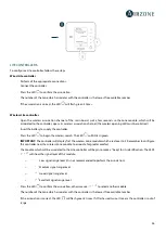
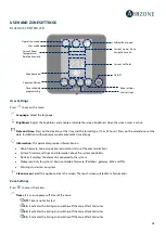
Page 38: ...isplays the elements connected to the system Webserver Only for system 1 Main controller firmware IP address gateway MAC and PIN Warnings and errors on system Clean screen Select this option to clean...

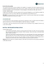
Page 39: ...available modes are Cool The conditioning unit will start a cooling cycle any time that any zone is in cool demand TSet Point T room Heat Enables the heating cycle whenever a zone is in heating deman...

Page 40: ...ablished limit temperature 35 C 95 F in cooling mode and 10 C 50 F in heating mode generating demand with the previous set point temperature before activating the vacation mode When interacting with t...

Page 41: ...cation status System firmware settings and information about the system controllers Devices displays the elements connected to the system Webserver Only for system 1 Main controller firmware IP addres...

Page 42: ...huts completely Note If you change this parameter all the dampers of the installation will be affected Auxiliary Heat This menu is used to enable disable the auxiliary heat By default the auxiliary he...

Page 43: ...ce ID 1000 Port 47808 IP Address DHCP Supply temperature only available in installations with Airzone VAF 10 KOhm NTC thermistor This option allows the system demand to be ignored if the supply temper...

Page 44: ...has effect on the zone module if it is associated to a controller it does not operate in secondary zone modules When this contact is on if the zone is empty for over 5 minutes the Timer 90 feature is...

Page 45: ...tion independently of whether the latter is an electric or water unit for the air in a zone or for an individual AC unit Occupancy contact It determines the state of the module of a zone based on the...

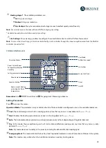
Page 46: ...It indicates the Heat supply function of the Cool mode is enabled Low Battery Lite only Blueface Low battery warning Informs about the involved zone when the icon is pressed Note For Lite controllers...

Page 47: ...47 AZVAFDAMPERxxC AZVAFZMRADC AZVAFZMOxxxC...

Page 48: ...of range 2 Module status Correctly powered 3 Module status Proper operation of the LED of wireless communication 4 Restart the zone and re associate it with the system To do this press and hold on an...

Page 49: ...ltage between the poles A and B is about 0 65 Vdc 5 Restart the zone and re associate it with the system Blueface controllers Press on Reset to restart the device If the error persists press and hold...

Page 50: ...e zone ceases to measure the room temperature therefore the zone cannot generate demand Proceed to replace it of the device or sent it for repair check if it is produced by the controller s probe or i...

Page 51: ...unit from the controller of its manufacturer To solve this incident check 1 Verify if the Air unit is powered To do this check the controller of the AC unit is ON 2 Verify the AC unit operates proper...

Page 52: ...rror between Control board and Relay Radiant Heat Control Module The device cannot be controlled by the system To solve this incident check 1 Status of the module Correctly powered 2 Status of the mod...

Page 53: ...s incident check 1 Connection Check the polarity of the connectors of the module and the controller 2 Wiring Check that the voltage between the poles A and B is about 0 65 Vdc 3 Wiring Verify that the...

Page 54: ...54 AZVAFDAMPERxxC AZVAFZMRADC AZVAFZMOxxxC...

Page 55: ...necessary to relocate it as it was out of range 2 Module status Correctly powered 3 Module status Proper operation of the LED of wireless communication 4 Restart the zone and re associate it with the...

Page 56: ...B is about 0 65 Vdc 5 Restart the zone and re associate it with the system Remember To reset to factory values of any Lite controller turn up the microswitch 8 and place the controller on the base aga...

Page 57: ...e module with XXX communication AZVAFZMOXXXC AZVAFZMOXXXR Relay Radiant Heat control module AZVAF5OUTPUTS Airzone Communication Gatways AZX6QADAPT xxx Controller Gateway AZX6GTC xxx Communication gate...

Page 58: ...58 NAVIGATION TREES BLUEFACE CONTROLLER NAVIGATION TREE...

Page 59: ...59 THINK CONTROLLER NAVIGATION TREE Remember Use to confirm and for going back if browsing submenus...

Page 60: ...Parque Tecnol gico de Andaluc a C Marie Curie 21 29590 Campanillas M laga Espa a Phone 34 900 400 445 Fax 34 900 400 446 http www myzone airzoneusa com...

Reviews: