


5
2.2 Installing the unit
Before starting installation select a suitable location for the antenna splitter.
The unit is intended for installation below deck in a dry location. When
locating the unit you should consider:
•
Routing of power and antenna cables to the unit.
•
Provision of sufficient space behind the unit for cable connections.
•
Maintaining the compass safe distance of 0.5m.
•
Visibility of the front panel indicators.
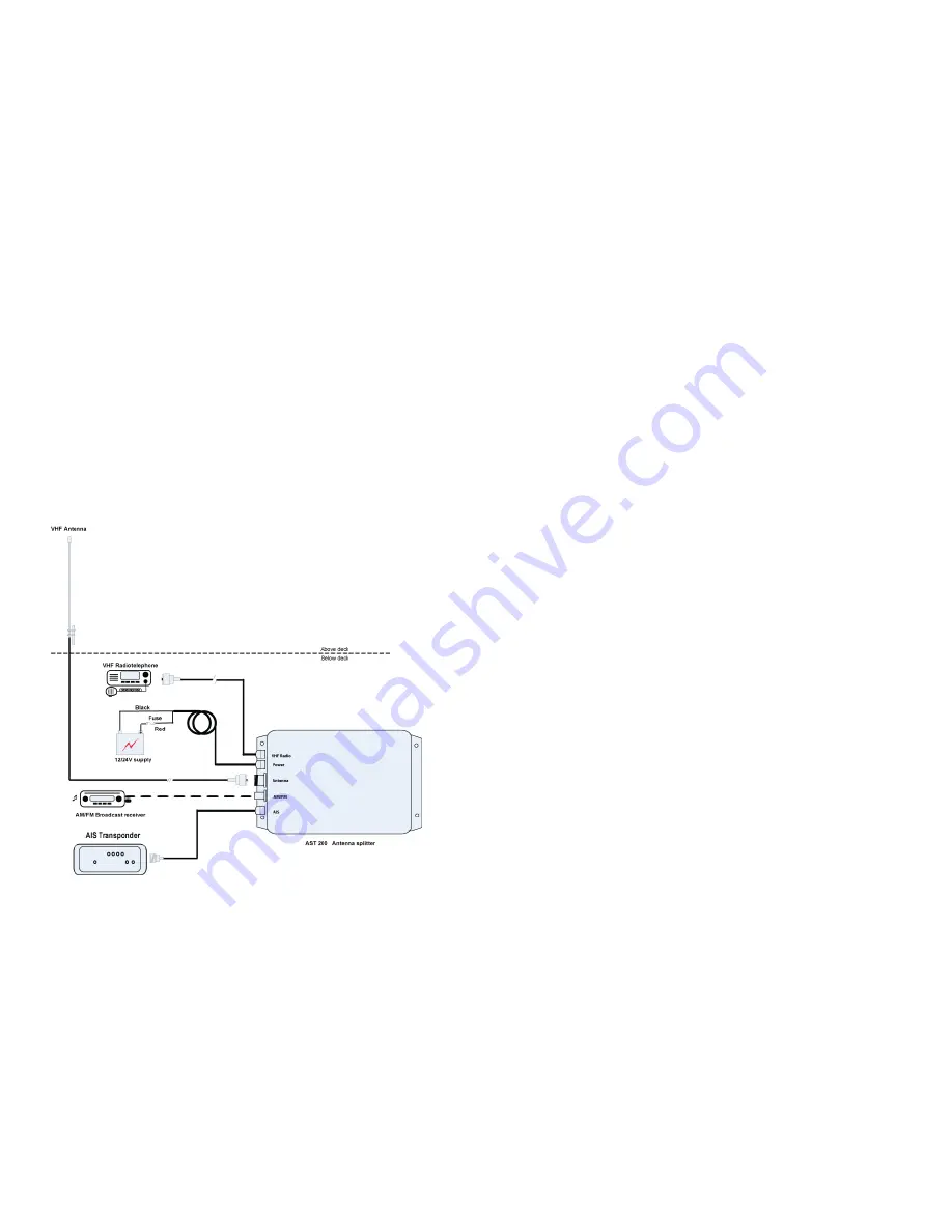
Installation diagram
6
Installation step 1
•
Secure the antenna splitter to a flat surface in the selected location.
Use four 5mm wood screws or other fixings suited to the material
the unit is being fixed to.
•
The unit may be installed in any orientation.
Installation step 2
Make the electrical connections to the antenna splitter as follows:
•
Remove the VHF antenna cable connection from your VHF Radio
and connect it to the connector labelled ‘Antenna’.
•
Connect the 1m cable marked “VHF Radio” to your VHF
Radiotelephone antenna connection.
•
Connect the 1m cable marked “AIS” to your AIS Transponder
antenna connection..
•
Optionally connect the antenna input of an FM Broadcast receiver
to the connector labelled ‘AM/FM’.
•
Connect 12VDC or 24VDC power supply to the power cable.
o
The red wire should be connected to the positive power
supply connection via a 1A rated fuse or circuit breaker.
o
The black wire should be connected to the negative power
supply connection.
Installation step 3
Apply power and verify the unit is operating:
•
Apply power to the antenna splitter, AIS Transponder and VHF
radiotelephone.
www.busse-yachtshop.de | info@busse-yachtshop.de


