– 11 –
8 8
A
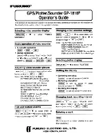
Resistor Code
Chip Resistor Part Coding
Figure
Value of resistor
Chip resistor
Wattage
Type
Tolerance
1/16W
1/10W
1/8W
1608
2125
3216
5%
5%
5%
CJ
CJ
CJ
Form
L
W
t
1.6
0.8
0.45
2
1.25
0.45
3.2
1.6
108
118
128
: A
: A
CHIP RESISTOR PART CODE
0.55
Resistor Code
Dimensions (mm)
Symbol
1/16W
1005
5%
CJ
1.0
0.5
0.35
104
L
t
W
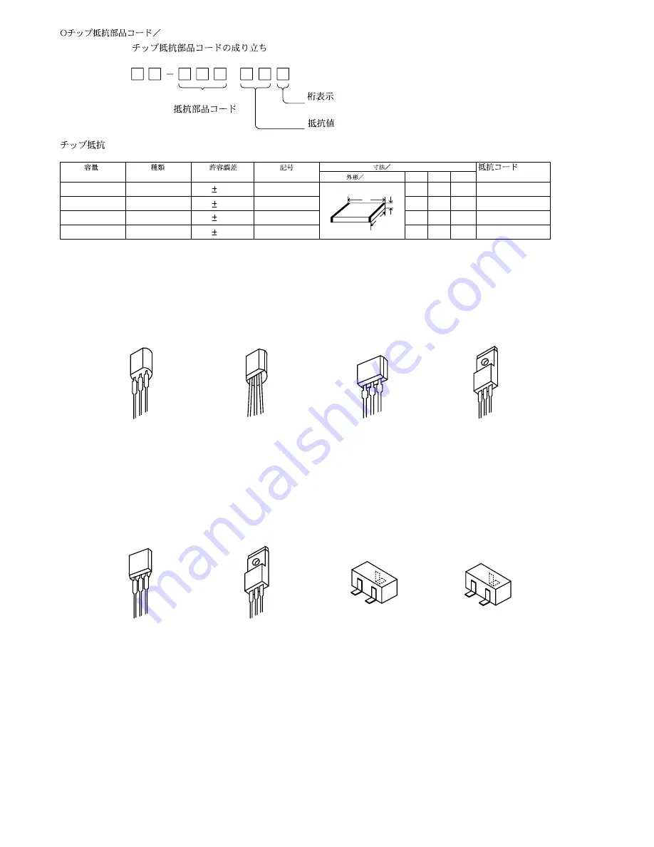
TRANSISTOR ILLUSTRATION
E C B
CD1585
CSA952
CSC4115
KTA1266
KTC3198
KTC3199
E C B
CC5551
2SB1370
2SB1588
2SD2439
2SA933
DTC114ES
2SB1237
E C B
B C E
2SK3053
G D S
E
B
C
2SA1235
2SC2714
2SC3052
2SD1306
CMBT5401
CMBT5551
E C B
KRA102
KRA104
KRA107
KRC102
RT1P141C
S
G
D
2SJ461-T1
2SK2158
Summary of Contents for CX-ZL900
Page 13: ...SCHEMATIC DIAGRAM 1 MAIN 1 3 AMP SECTION VM 13 ...
Page 14: ...SCHEMATIC DIAGRAM 2 MAIN 2 3 DECK SECTION HEAD 1 HEAD 2 14 ...
Page 15: ...SCHEMATIC DIAGRAM 3 MAIN 3 3 TUNER SECTION 15 ...
Page 17: ...SCHEMATIC DIAGRAM 4 MICON DECK 17 ...
Page 20: ...SCHEMATIC DIAGRAM 5 CNTL MIC KEY CD DK1 LED DK2 LED 20 ...
Page 22: ...SCHEMATIC DIAGRAM 6 AMP 1F 22 ...
Page 24: ...SCHEMATIC DIAGRAM 7 PT 24 ...
Page 28: ... 28 IC BLOCK DIAGRAM ...
Page 29: ... 29 ...
Page 30: ... 30 ...
Page 31: ... 31 ...
Page 32: ... 32 ...
Page 33: ... 33 FL BJ751GNK GRID ASSIGNMENT ANODE CONNECTION GRID ASSIGNMENT ...
Page 34: ... 34 ANODE CONNECTION ...