77
DECK MECHANISM DISASSEMBLY
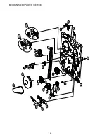
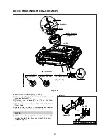
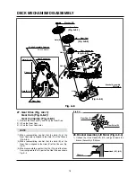
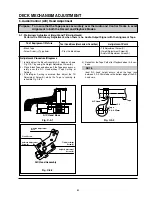
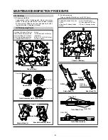
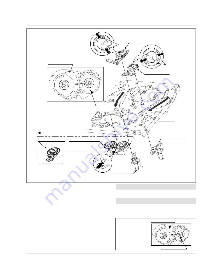
Gear Assembly P3
Gear Assembly P2
Base Assembly P2
Base Assembly P3
Arm Assembly Idler
(For Normal Models)
(
For Jog Shuttle Models
)
Arm Assembly Idler Jog
or
Optional Parts
(H3)
Gear Assembly P2
Gear Assembly P3
(A)
(A)
(B)
(B)
Chassis
H1
H2
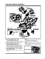
Fig. A-10
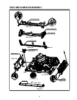
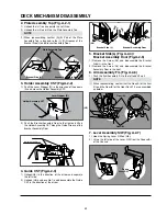
31. Gear Assembly P3 (Fig. A-10-1)/
Gear Assembly P2 (Fig. A-10-2)
1) Unhook the two Hooks(H1) and lift up the Gear Assembly P3.
2) Unhook the two Hooks(H2) and lift up the Gear Assembly P2.
32. Base Assembly P3 (Fig. A-10-3)/
Base Assembly P2 (Fig. A-10-4)
1) Move the Base Assembly P3 in the direction of the arrow of
the Chassis Hole(A) and push down the Base Assembly P3.
2) Move the Base Assembly P2 in the direction of the arrow of
the Chassis Hole(B) and push down the Base Assembly P2.
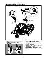
33. Arm Assembly Idler or Arm Assembly
Idler Jog(Fig. A-10-5)
1) Unhook the Hook(H3) and push down the Arm Assembly
Idler Jog.
1) Arm Assembly Idler is for Normal Models.
2) Arm Assembly Idler Jog is for Jog Shuttle Models.
1) When reassembling, confirm that the (A) Part of the Gear
Assembly P3 is aligned to the (B) Part of the Gear Assembly
P2 as shown below.
NOTE
NOTE
Gear Assembly P3
Gear Assembly P2
(A)
(B)
(Fig. A-10-1)
(Fig. A-10-2)
(Fig. A-10-4)
(Fig. A-10-3)
(Fig. A-10-5)
(Unloading Condition)

