DECK MECHANISM DISASSEMBLY
Arm
Assembly
Pinch
Opener Lid
Base Assembly P4
Support CST
Arm Assembly T/up
(A)
(B)
(C)
(D)
Spring
Arm T/Up
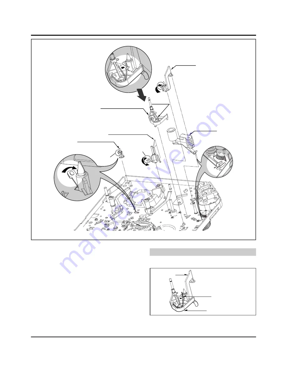
Fig. A-5
54
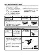
15. Support CST (Fig. A-5-1)
1) Break away the (A) part shown above Fig. A-5-1 from the
Embossing of the Chassis in the clockwise direction, and
lift up the Support CST.
16. Base Assembly P4 (Fig. A-5-2)
1) Break away the (B) part shown above Fig. A-5-2 from the
Embossing of the Chassis in the counterclockwise direc-
tion and lift up the Base Assembly P4.
17. Opener Lid (Fig. A-5-3)
1) Hook the Spring Arm T/up on the Split digged under the
Arm Assembly T/up.(Refer to Fig.A-5-4(D)).
2) Break away the (C) Part of the Opener Lid from the
Embossing of the Chassis in the Clockwise direction and
lift up the Opener Lid.
18. Arm Assembly T/up (Fig. A-5-4)
1) Confirm that the Spring Arm T/up is placed as above
(No.17.1).
2) Lift up the Arm Assembly T/up.
(1) When reassembling, unhook the Spring Arm T/up Shown
above (No.17.1) to the original position.
19. Arm Assembly Pinch (Fig. A-5-5)
1) Lift up the Arm Assembly Pinch.
NOTE
Opener Lid
Spring Arm T/up
Arm Assembly T/up
(Fig. A-5-3)
(Fig. A-5-4)
(Fig. A-5-1)
(Fig. A-5-2)
(Fig. A-5-5)


