– 39 –
SERVICE MODE
1. Starting the Service Mode
Short the service jumpers on the front C.B to start the service
mode. Each time it is shorted, the mode changes follows.
Service Mode 1
→
2
→
3
→
Normal Mode
2. Releasing the Service Mode
If the mode switching operation is performed after starting,
the normal mode is entered after mode 3 (the service mode is
released). The service mode is also released when the power
cord is unplugged from the AC outlet and plugged in again.
3. Overview
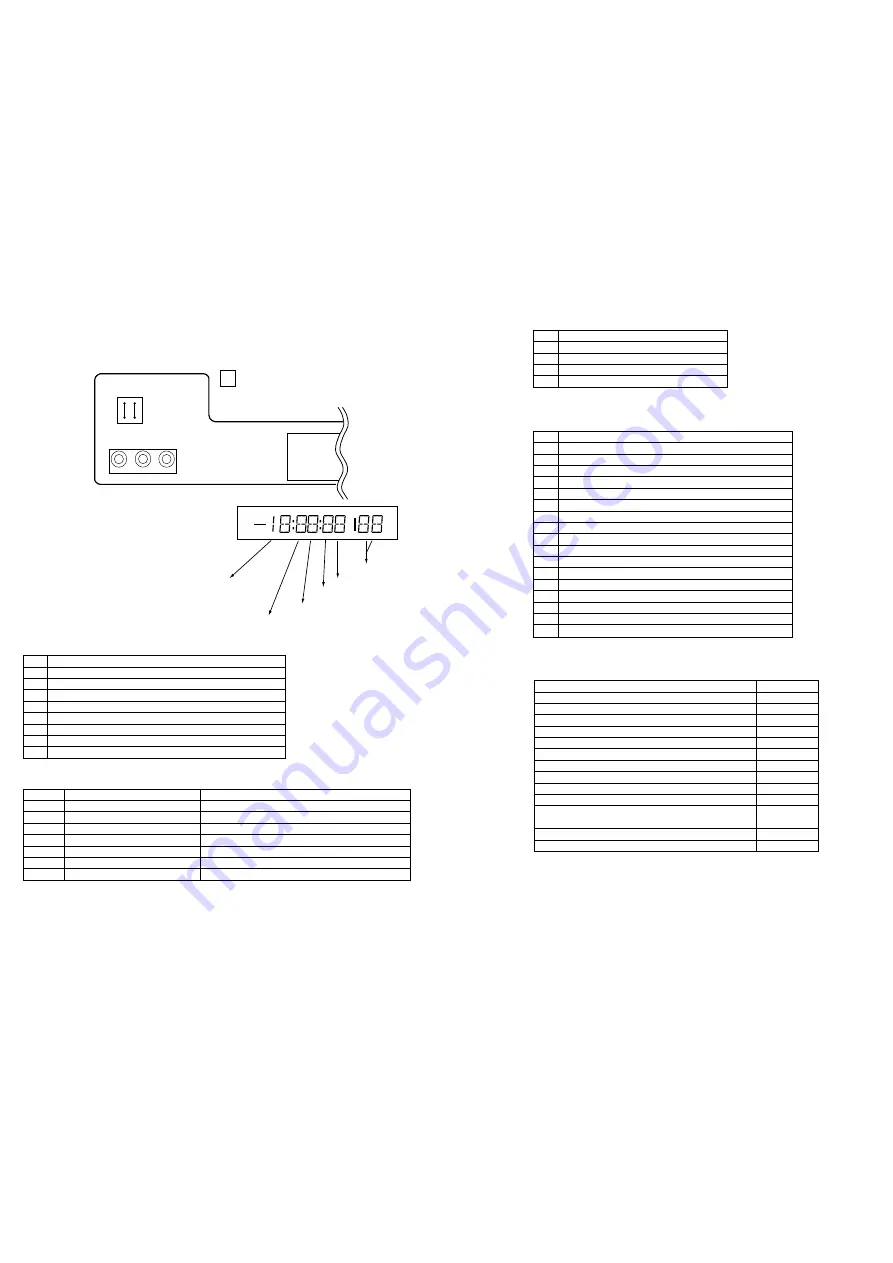
1. Service Mode 1
The following data is displayed in the FL display (FL 101).
a)
Service mode No.
b)
Mechanism position
c)
Error code
d)
Top/end sensor data
e)
Operation mode
f)
Key data
a) Mechanism Position
Code
Operating Mode Contents
0
LOADING/UNLOADING
2
THREADING/UNTHREADING
4
REVERSE (PINCH ON)
6
FORWARD (PINCH ON)/STAND BY
8
STOP (WITH MAIN BRAKE)
A
FF/REW 1 (HIGH SPEED)
C
FF/REW 2 (LOW SPEED)
F
OTHER POSITIONS
b) Error Code
When a mechanism error has occurred, the error code will remain displayed for one hour. Also, if other mechanism errors have occurred,
the error display will be changed. After making repairs, reset the error code using the method noted below.
During P-ON, drop the microcomputer's reset pin 76 to GND (approximately 1 second).
Error Code
Contents Of Errors
State
0
NORMAL
-
1
DRUM ERROR
WHEN DRUM FG DOES NOT CHANGE OVER 2SEC
2
T-REEL ERROR
WHEN T-REEL DOES NOT CHANGE OVER 6SEC
3
S-REEL ERROR
WHEN S-REEL DOES NOT CHANGE OVER 6SEC
4
LOADING/UNLOADING ERROR
WHEN IT CAN’T FINISH CASSET IN/OUT WITHIN 5 SEC
5
THREADING/UNTHREADING ERROR
WHEN IT CAN’T NEXT POSITION FOR LOAD WITHIN 6SEC
9
PROTECT ERROR
WHEN PRT OR M-PRT IS “L” OVER 1SEC AT POWER ON
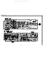
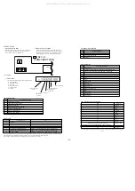
C FR2 C.B
(COMPONENT SIDE)
FL101
J751
SERVICE
a) Service mode No.
"1" flashes.
b) Mechanism
position
c) Error code
d) Top/end sensor
information
e) Operation mode
f) Key information
c) Top/End Sensor Information
Code
Top/End Information
0
TAPE TOP AND END DETECTION
1
TAPE TOP DETECTION
2
TAPE END DETECTION
3
NORMAL
d) Operation Mode
Code
Operating Mode Contents
0
STAND BY
1
WHEN 5 MINUTES HAVE ELAPSED IN THE STAND-BY MODE,
THE DRUM'S ROTATION STOPS AND THIS IS DISPLAYED
2
REW
3
REV
4
FF
5
CVE
6
PLAY
7
STILL/SLOW
8
X2 PLAY
9
TAPE IN P-OFF
A
REV PLAY
B
REV STILL/REV SLOW
C
REC
D
REC PAUSE
E
P-OFF EJECT
F
P-ON EJECT
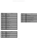
Code
Key Name
00
POWER
48
EJECT
15
PLAY
F6
DIMMER
1A
STOP
17
PAUSE
14
REC
40
CH (+)
41
CH (-)
89
OT PB
64/65/66/69/6A/6C/6D/74/75/76/79/7A/7C/7D
SH FWD RVS
*THE DISPLAY WILL DIFFER DEPENDING UPON THE SPEED
B6
THEATER
FF
KEY OFF
e) Key data (with remote controller key)
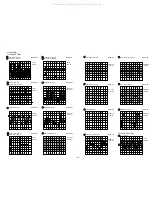
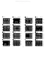
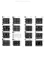
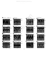
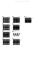
Remote key input other than those listed above can be checked with the FL light shown in the figure
below.
All manuals and user guides at all-guides.com
Summary of Contents for HV-FX8700
Page 3: ...3 All manuals and user guides at all guides com...
Page 12: ...12 C WIRE HARNESS DIAGRAM All manuals and user guides at all guides com...
Page 13: ...BLOCK DIAGRAM 1 SYSCON SERVO 13 All manuals and user guides at all guides com...
Page 14: ...BLOCK DIAGRAM 2 VIDEO 14 All manuals and user guides at all guides com...
Page 16: ...16 BLOCK DIAGRAM 4 TUNER All manuals and user guides at all guides com a l l g u i d e s c o m...
Page 17: ...17 BLOCK DIAGRAM 5 MPX All manuals and user guides at all guides com...
Page 18: ...BLOCK DIAGRAM 6 CANAL 18 SWITCH Q610 WIDE All manuals and user guides at all guides com...
Page 19: ...19 BLOCK DIAGRAM 7 POWER PS All manuals and user guides at all guides com...
Page 22: ...22 SCHEMATIC DIAGRAM 2 MAIN 2 4 VIDEO SECTION All manuals and user guides at all guides com...
Page 23: ...23 SCHEMATIC DIAGRAM 3 MAIN 3 4 HIFI SECTION All manuals and user guides at all guides com...
Page 25: ...25 SCHEMATIC DIAGRAM 4 FR1 FR2 All manuals and user guides at all guides com...
Page 27: ...27 SCHEMATIC DIAGRAM 6 REAR 2 2 CANAL SECTION All manuals and user guides at all guides com...
Page 29: ...29 SCHEMATIC DIAGRAM 7 TUNER All manuals and user guides at all guides com...
Page 30: ...30 SCHEMATIC DIAGRAM 8 MAIN 4 4 POWER SECTION All manuals and user guides at all guides com...
Page 32: ...32 SCHEMATIC DIAGRAM 10 MPX All manuals and user guides at all guides com...
Page 38: ...38 IC BLOCK DIAGRAM All manuals and user guides at all guides com...

