

– 31 –
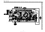
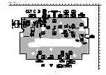
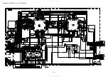
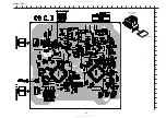
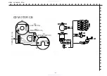
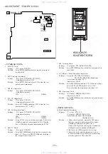
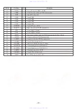
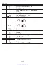
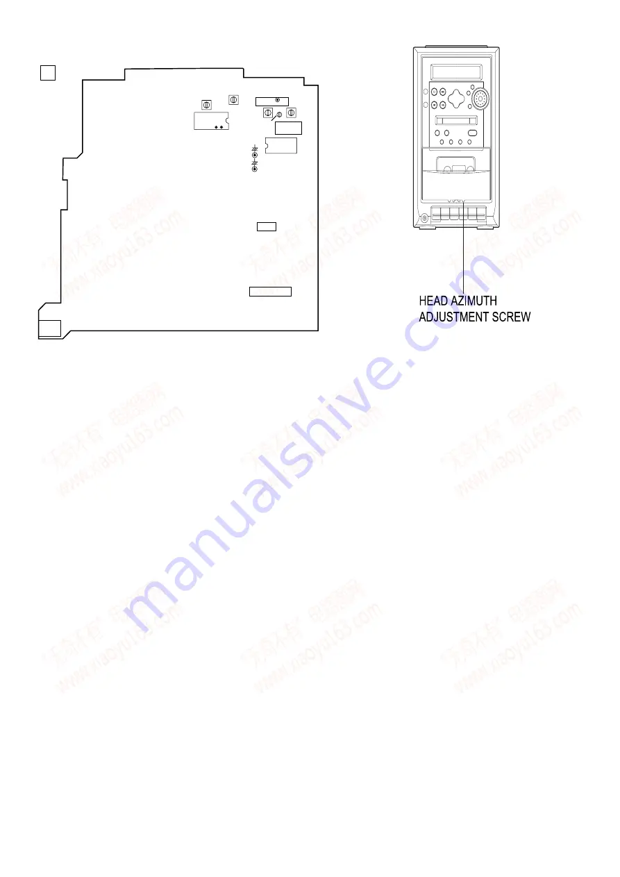
ADJUSTMENT <TUNER / DECK>
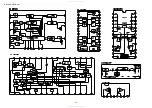
TP4 (VT)
FFE801
L981
1
4
IC721
+
+
TP7(Rch)
C786
TP8(Lch)
C785
TP6
TP5
28
26
IC771
L772
L771
IC201
IC202
J201
MAIN C.B
A
L941
L942
TC942
< TUNER SECTION >
1. MW VT Check
Settings :
• Test point : TP4 (VT)
Method :
Set to MW 1602kHz and check that the test point is
less than 5.6V.
2. MW Tracking Adjustment
Settings :
• Test point : TP7 (RCH), TP8 (LCH)
• Adjustment location : L981
Method :
Set to MW 999kHz and adjust L981so that the test
point becomes maximum.
3. AM IF Adjustment
Settings :
• Test point : TP7 (RCH), TP8 (LCH)
• Adjustment location:
L772 .................................................... 450kHz
4. LW VT Adjustment
• Test point : TP4 (VT)
• Adjustment location : L942
Set to LW 153kHz and adjust L942 so that the test
point becomes 1.3V
• Test point : TP7 (RCH), TP8 (LCH)
• Adjustment location :
L941 .................................................... 153kHz
TC942 .................................................. 285kHz
Set up TC942 to center before adjustment. The level at
153kHz is adjusted to maxinum by L941. Then the
level at 285kHz is adjusted to maxinum by TC942.
6. FM VT Check
Settings :
• Test point : TP4 (VT)
Method :
Set to FM 108MHz and check that the test point is less
than 8.2V .Then set to FM 87.5MHz and check that
the test poit is more than 1.5V.
7. FM Tracking Check
Settings :
• Test point : TP7 (RCH), TP8 (LCH)
Method :
Set to FM 98MHz and check that the test point is less
than 18dB.
8. DC Balance / Mono Distortion Adjustment
Settings : • Test point : TP5, TP6 (DC balance)
TP7 (RCH), TP8(LCH)(Distortion)
• Adjustment location : L771
• Input level : 54dB
Method :
Set to FM 98MHz and adjust L771 so that the voltage
between TP3 and TP4 becomes 0V
±
0.04V.
Next, check that the distortion is less than 1.5%.
9. FM Separation Check
Settings :
• Test point : PHONE JACK (J201)
• Input level : 54dB
Method :
Set to FM 98MHz and check that the test point is more
than 20dB.
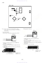
< DECK SECTION >
10. Head Azimuth Adjustment
Settings :
• Test tape : TTA–330
• Test point : PHONE JACK (J201)
• Adjustment location : Head azimuth
adjustment screw
Method :
1) Connect the L positive terminal to CH1 probe
(positive side) of oscilloscope and L negative
terminal to CH1 probe (negative side).
Connect the R positive and negative terminals to
CH2 probe same condition as CH1 probe.
2) Play back the 10kHz signal of the test tape.
3) Adjust the head azimuth adjustment screw to
become maximum waveform in the oscilloscope
and same phase for CH1 and CH2.
www. xiaoyu163. com
QQ 376315150
9
9
2
8
9
4
2
9
8
TEL 13942296513
9
9
2
8
9
4
2
9
8
0
5
1
5
1
3
6
7
3
Q
Q
TEL 13942296513 QQ 376315150 892498299
TEL 13942296513 QQ 376315150 892498299


